Do you have a question about the Honeywell MA-2000 and is the answer not in the manual?
Information required for the proper use of the products, including transport, storage, installation, and mounting guidelines.
Explanation of pictograms indicating safety information and guidelines, and information on product dismantling.
List of related documents for the MA-2000 system, including installation and commissioning manuals.
Procedures to avoid equipment damage, including environmental conditions and handling of components.
Information on compliance with EN 54-2 and EN 54-4 requirements, including optional functions.
Procedures for inspecting transport damage and essential safety precautions like electrical shock and ESD.
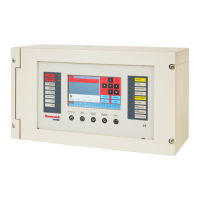
Overview of the MA-2000 control unit's technical specifications, power supply, detection lines, and main functions.
Essential guidelines for installation, including qualified personnel, environment, mounting, and safety warnings.
Details on main power supply, internal power supply, and battery charger section specifications.
Description of system components including PSU board, front board, and main connection board.
Details on CPU board jumpers, DIP switches, and board setup for configuration.
Instructions on how to set relay outputs as NO/NC or supervised.
Connection diagrams for general fault and alarm relays with different device types.
Description of the MA-BST-C CAN-BUS amplifier card and its function in extending network distance.
Example wiring for node-to-node network connections.
Example installation of single CAN-BUS amplifier cards on HLSPS25 PSU.
Specifications for CAN-BUS network cables, including type, core, and shield.
Technical specifications for detection line connection cables, including type and section.
Example of a closed line (style 6 loop) with screen termination.
Procedures for testing line resistance, insulation, and voltage using a digital multi-meter.
Steps for system test and commissioning, including power supply connection and front panel checks.
Procedures for periodical maintenance, including AC mains, battery, and alarm line checks.
List of available spare parts, their part numbers, and essential safety information for replacement.
Instructions for reinstalling and recommissioning the user board after replacement.
Preparation steps for replacing the main board and LCD.
Recommissioning steps after replacing the main board and LCD.
| Type | Security System |
|---|---|
| Model | MA-2000 |
| Manufacturer | Honeywell |
| Battery Backup | Yes |
| Zones | 8 |
| Communication | POTS (Plain Old Telephone Service) |
| Compatibility | Honeywell Ademco Contact ID |