MA-2000
M-167.1-MA2000-EN / 06.2022 23
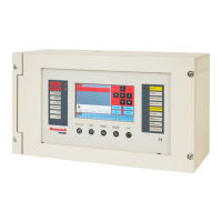
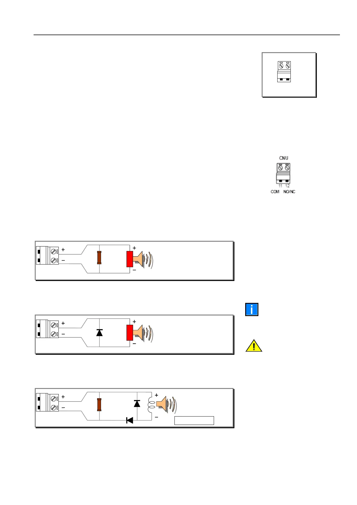
EOL resistor or the diode
only on last sounder of
the line.
Polarity displayed are in
Alarm condition, at idle
condition, they are
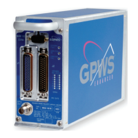
6.3.2 General Fault relay
The General Fault relay is usually in energized state. It is de-energized in
Fault condition. This output is available in free voltage.
Contact range: max 30 V AC / DC, 1 A, Non-inductive loads
Setting of the general fault output with N.O. contact (Jumper JGST).
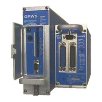
Main Fault output connections
(refer to basic board topography)
6.3.3 General Alarm relay
The General Alarm relay is usually in energized state. It is de-energized
in Fault condition. This output is available in free voltage.
Contact range: max 30 V AC / DC, 1 A, Non-inductive loads.
Setting of the general fault output with N.O. contact (Jumper JALL)
Main Alarm output connections
(refer to basic board topography)
Polarized devices balanced with resistor (electronic sirens, etc.)
Polarized devices balanced with diode (electronic sirens, etc.)
Non-polarized devices balanced with a resistor (Bells, relays, etc.)
 Loading...