This document serves as an Operating Instructions and Log Book for Fire Control and Repeat panels, specifically covering the Conventional 2, 4, and 8 Zone panel range. It is intended for use by the End User and should be kept in a secure yet accessible location near the panel. The End User is responsible for maintaining the Log Book.
Function Description:
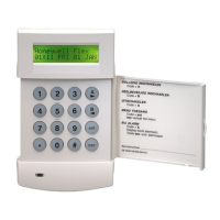
The fire alarm system is designed to detect fire conditions, alert occupants, and, if configured, initiate auxiliary equipment and contact the Fire Brigade. The control panel provides visual and audible indications for various system states, including fire, fault, disablement, and test modes. It features a numeric keypad for coded access to controls and functions.
Controls and Indicators:
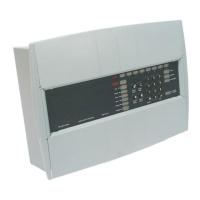
The panel includes several controls and indicators to manage and monitor the fire alarm system:
- ZONE Fire, Fault or Disablement indications: These LEDs (red and yellow) indicate the status of each zone (1-8). A red light signifies a zone fire (steady or flashing), a flashing yellow light indicates a zone fault, and a lit yellow light with the "Disabled" indicator shows a disabled zone.
- FIRE (red): Lights up when the system detects a fire.
- Fault (yellow): Lights up or flashes to indicate a system fault requiring rectification.
- System (yellow): Indicates a fault in the panel's processor when lit.
- Power (green): Normally lit to indicate a healthy power supply.
- Earth (yellow): Lights up or flashes to indicate an Earth Fault on the system.
- Sounder (yellow): Flashes with a fault indicator for a sounder fault, or lights up with the "Disabled" indicator if sounders are disabled.
- Disabled (yellow): Illuminates with sounder or zone indicators to show a disabled condition.
- Test (green): Lights up when the panel is in Test mode.
- Delay (yellow): Lights up when a delay is active before system alarms activate after fire detection.
- Access/Function (yellow): Flashes when the Shift key is pressed and lights up when coded functions are accessed.
- Numeric Keypad (0-9, A): Used for entering numeric data and access codes.
- Shift/Function Key (A): Provides access to the main functions of the panel.
- Display Test Key: Initiates a sequence to illuminate all indicators for checking, typically requiring coded access.
- Cancel System Buzzer: Stops the internal buzzer sound, usually requiring coded access.
- System Reset: Returns the system to its normal operating state after an alarm or fault, requiring coded access. If uncleared fires or faults exist, these conditions will re-occur.
- Sound Alarms: Activates all system alarms, intended for emergencies or sounder tests, requiring coded access. This button does not action the auxiliary relay.
- Silence Alarms: Silences system alarms, intended for use after an emergency, requiring coded access.
Operating Instructions:
- Normal Condition: The panel should show a healthy indication with only the green "Power" light lit.
- Fire Condition: Upon automatic fire detection, the "FIRE" light and relevant "Zones-fire" light will illuminate, the buzzer will sound continuously, system alarm sounders will activate, and auxiliary equipment/Fire Brigade link may be actuated if configured.
- After Emergency: To silence alarms and reset the system, enter the 3-digit code, press "Silence Alarms," investigate the cause, ensure smoke/heat have cleared, replace broken call point glass/reset elements, then press "System Reset."
- Sound/Resound Alarms: Enter the 3-digit code and press "Sound Alarms."
- Silence Alarms: Enter the 3-digit code and press "Silence Alarms."
- Fault Conditions: A "Common Fault" light may illuminate, accompanied by other fault indicators, and the buzzer will sound intermittently (except for system fault, which is continuous). To cancel the fault buzzer, enter the 3-digit code and press "Cancel Buzzer." Fault indications extinguish automatically once rectified.
- Display Test: Enter the 3-digit code, press "Shift" then "Display" to illuminate all LEDs and sound the buzzer.
- Test Mode A: Enter the 3-digit code, press "A" and "3" followed by the zone number. This mode triggers a manual call point or detector in the test zone for 10 seconds, followed by a system reset, without activating full alarms. The "Test" indicator and respective zone fault indicator will light.
- Test Mode B: Enter the 3-digit code, press "A" and "4" followed by the zone number. This mode triggers system alarms for 2 seconds and a fire indication for 10 seconds, followed by a system reset. The "Test" indicator and respective zone fault indicator will light.
- Cancel Test Mode A/B: Enter the 3-digit code, press "A" and "5" followed by the zone number.
- Exit Access Level 2: Press "A" and "0."
- Disable a Zone: Enter the 3-digit code, press "A" and "1" followed by the zone number. The zone fault and disabled indicators will light. A fire in a disabled zone will not trigger a fire condition.
- Enable a Zone: Enter the 3-digit code, press "A" and "2" followed by the zone number.
- Disable Sounders: Enter the 3-digit code, press "A" and "1" followed by "0." The sounder and disabled indicators will light.
- Enable Sounders: Enter the 3-digit code, press "A" and "2" followed by "0."
- Set/Unset Delay Mode: Enter the 3-digit code, press "A" and "6." This toggles the delay mode, where the "Delay" lamp lights when active.
Usage Features:
- User Responsibility: The End User is responsible for ensuring the system is regularly tested and maintained according to BS5839 Part 1, understanding controls and indications, and maintaining documentation.
- Daily Inspection: Check for normal indications, address previous faults, record all events in the Log Book, and ensure no changes in area usage.
- Weekly Testing: Test a different manual call point each week to ensure alarm operation. Contact the alarm receiving centre before and after the test.
- Quarterly Inspection: A trained maintenance engineer should inspect the system quarterly.
- False Alarm Limitation: Investigate false alarms. For systems with less than 40 detectors, investigate two false alarms in 12 months. For systems with more than 40 detectors, investigate one false alarm per 20 detectors in 12 months, or two or more from a single device.
- Manual Call Point Testing: Requires a call point test key. Push the key through the hole in the underside of the call point to activate it. Alarm sounders will activate.
- Replacing Broken Glass/Resetting Resettable Element: Follow specific procedures for the call point type, taking precautions against injury.
Maintenance Features:
- Servicing: All servicing work must be carried out by a servicing organisation or suitably trained personnel.
- Battery Replacement: Maintenance-free lead-acid batteries have a useful life of up to 5 years. Replacement is recommended at 4-yearly intervals from commissioning. Only trained service personnel should replace batteries.
- Fault Rectification: All fault rectification work must be done by suitably qualified personnel.
- Log Book: A log book is provided to record system events, maintenance work, and system configuration details, including:
- Address of protected premises, responsible person, system designer, installer, commissioning, acceptance, verification, and maintenance contract details.
- Contact information for maintenance.
- List of components requiring periodic replacement.
- Zone number and description.
- AL2 password.
- Events Log: Records events like tests, fire alarm signals, and faults, including date, time, zone, device, action required, completion date, and initials.
- Maintenance Work Log: Records date, time, zone, device, reason for work, work carried out, further work required, and signature.
- System Configuration Record: Documents deviations from standard factory settings for detection, zone circuits, sounders, system reset, auxiliary relays, and access levels.
- Delay mode setting (in minutes).
- Repeat panel information: EEPROM location, EEPROM data, and name of the area where the panel is installed.
- WEEE Directive: Packaging, product, and batteries should be disposed of via a suitable recycling centre, not normal household waste, and not burned.
Important Technical Specifications (from CE marking and EN standards):
- Manufacturer: Gent by Honeywell (Novar Systems Limited), Honeywell Life Safety Systems, 140 Waterside Road, Hamilton Industrial Park, Leicester, LE5 1TN, United Kingdom.
- CE Marking: 0086
- Product Numbers and DoP (Declaration of Performance):
- 13270-01LB, 13270-02LB, 13270-04LB, 13270-08LB (DoP: 053-CPR-2013)
- 13270-01SP, 13270-02SP, 13270-04SP, 13270-08SP (DoP: 054-CPR-2013)
- 75585-02RS, 75585-04RS, 75585-08RS (DoP: 056-CPR-2013)
- Standards Compliance: EN54-2: 1997 +A1:2006, EN54-4: 1997 +A1: 2002, A2 2006.
- Intended Use: For use in fire detection and fire alarm systems in and around buildings.
- Website for Performance Details: www.gent.co.uk
- Contact Information:
- Telephone: +44 (0) 116 246 2000
- Tech. Support: www.gentexpert.co.uk
- Fax (UK): +44 (0)116 246 2300
This manual provides essential information for the End User to operate and maintain the fire alarm system effectively and in compliance with relevant standards.