EasyManua.ls Logo

Honeywell GENT Nano panel-based User Manual

Honeywell GENT Nano panel-based
85 pages
To Next Page IconTo Next Page
Page #1 background imageLoading...
Page #1 background image
4188-949 issue 3_05/10_Nano Comms inst.
by Honeywell
Commissioning Instructions
Nano panel - based
Fire detection and alarm system
by Honeywell
POWERFAULT
FIRE
Tes t
Delay
Verify
Sounder Fault
Zone 2
Zone 6
Zone 10
Zone 14
Zone 3
Zone 7
Zone 11
Zone 15
Zone 4
Zone 8
Zone 12
Zone 16
Disablement
Zone 1
Zone 5
Zone 9
Zone 13
System Fault
Sound
Alarms
Silence
Alarms
Power Fault
Reset
Cancel
Buzzer
Sounder
Disablement
042bc
EN54 Parts 2 & 4
ISSUE 3
V2.xx

Table of Contents

Question and Answer IconNeed help?

Do you have a question about the Honeywell GENT Nano panel-based and is the answer not in the manual?

Honeywell GENT Nano panel-based Specifications

General IconGeneral
TypeFire Alarm Control Panel
CategorySecurity System
Event LogUp to 1000 events
Input Voltage230 VAC
Enclosure RatingIP30
TechnologyAddressable
ManufacturerHoneywell
Max Devices per Loop126 devices
Sounder Circuits2
Relay Outputs4 relay outputs
CommunicationRS485, Ethernet

Summary

Preliminary information

Safety information

Safety precautions for handling the control panel and its components.

System commissioning process

Backup

Regularly backing up system data to prevent loss during commissioning.

Loop wiring tests

Performing tests for short and open circuits on loop wiring.

Retrieve the device data to Commissioning tool

Retrieving device data from the panel to the commissioning tool.

Before powering up the Nano Panel

Actions to take before applying power to the panel.

Configuring the system using the Nano Commissioning Tool

Using the Nano Commissioning Tool for site-specific system configuration.

Power up

Steps for powering up the panel after initial checks.

Transmit the configured system to the Nano panel

Transferring the configured system data to the Nano panel.

Beam Sensor alignment

Aligning beam sensors using panel functions.

Loop Devices

Configuring interface units and powering up mains powered units on the loop.

Loop Device address allocation

Procedure for allocating addresses to devices on the loop circuits.

Installed system test

Conducting comprehensive tests on the installed system components and functions.

Factory default settings

External Wiring

Preparation for first power up

Loop circuit connect END 1 only

Power up

How to change the user PIN code (Password or Usercode)

Address allocation

Address allocation from Loop END 1

Steps for allocating addresses when connecting Loop End 1.

Address allocation from Loop End 2

Steps for allocating addresses when connecting Loop End 2.

How to manually 'Power-down' or 'Power-up' the loop

How to manually 'Start Detection' after manual power-up

How to view the 'Loop Map' and 'Enable / Disable' Devices

How to 'Find Devices' on the Loop circuit

How to 'Back-up' site data to Flash memory

How to 'Restore' configuration data from Flash memory

How to view 'Diagnostics' data

When to use the 'Repair' function on the loop circuit

Loop 'Short Circuit' test

Loop 'Ground Break' test

Loop 'Positive line' break test

Loop 'Earth fault' tests

To 'Save loop map' and make 'SAFE' device addresses

To 'Clear loop map' and 'UNSAFE' saved addresses from loop devices

Insertion of new devices on a 'Saved' loop map

How to view or change 'Device configuration'

Method 1 at access level 3 or above

Steps to view/change device configuration via panel menus.

Method 2 at access level 4

Steps to view device configuration using the loop map.

How to set 'Zone' label, mode and link to another zone

How to view 'Devices' assigned to a 'Zone' and change device configuration

How 'Cause and Effect' interact with 'Day and Night Modes'

How to setup zone for 'Immediate Cause and Effect'

How to setup zone for 'Delayed Cause and Effect'

How to set up 'Day mode' delays and timeout

How to set-up 'Sector' mode, label and activation

How to set-up 4-channel interface devices on the loop

How to view or print device 'Time averages'

How to view Sensor 'Condition Codes'

Condition Codes for S-Quad Sensors

How to set up an 'External Evacuate input'

How to set-up the 'Class Change input'

How to set up RS-232 and RS-485 serial and USB ports

How to change the 'Alarm Controls' settings

How to change the 'Signal' Settings

How to start or stop a 'Weekly test'

How to place the system in 'Commissioning mode'

How to enable/disable Master alarms, Fire relay and Evac. input

How to enable or disable and set a Sector activation control

How to return 'System Configuration' to factory default settings

How to return all 'Labels' to factory default settings

How to return the 'Configuration and Labels' to factory default settings

How to return all 'Access level PIN codes' to factory settings

How to upgrade the panel firmware from a SD card

How to back up all system configuration and labels to a SD card

How to back up all labels to a SD card

How to restore 'Config', 'Labels' or 'Logo' from a SD card

How to use a SD card to log 'Historic Events' for diagnostics

Tests on installed equipment

S-Quad Sensors

Testing S-Quad sensors, their sound/speech output, and sound levels.

Appendix A - Message Action List

Latching fault events

Lists fault events that require manual intervention to clear.

Appendix C - old Beam sensor

Start Align

Procedure to initiate beam alignment.
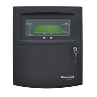
Related product manuals