External Wiring
The following procedures assume the Nano panel is installed.
¨
Remove the Screw cover j from the Outer cover to reveal the fixing screws
¨
Using the allen key k open the two fixing screws
¨
Open out the bottom edge of the Outer cover and lift it up and out l.
¨
Depending on the installation, the cables may be connected to respective terminals or left unconnected. If the cables are to be connected then straighten out the cable tails m and
then one-by-one connect each cable to the respective terminals.
4188-949 issue 3_05/10_Nano Comms inst. 11
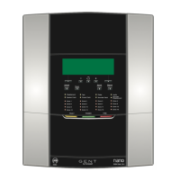
Nano panel based system
External Wiring
Outer Cover
Backbox
Screw cover
Allen Ke
POWERFAULT
FIRE
Tes t
Delay
Tes t
Sounder Fault
Zone 2
Zone 6
Zone 10
Zone 14
Zone 3
Zone 7
Zone 11
Zone 15
Zone 4
Zone 8
Zone 12
Zone 16
Disablement
Zone 1
Zone 5
Zone 9
Zone 13
System Fault
Sound
Alarms
Silence
Alarms
Power Fault
Reset
Cancel
Buzzer
Sounder
Disablement
MAINS
SUPPLY
Master
alarms 1
Master
alarms 2
LOOP 1
END 1
LOOP 1
END 2
Class
Change
Fire
Relay
 Loading...