EN
Model Assembly Continued
3 x 8mm
button head machine
B,C
B
A
C
Wing Installation
IMPORTANT: The integrated servo connectors are in the wing and fuselage.
Ensure that they slide together correctly.
1. Secure the wing halves into position using the included 3 x 8mm screws (C).
Disassemble in reverse order.
Propeller Installation
1. Install the Prop adapter, propeller, prop washer and nut.
2. Tighten the nut until the prop adaptor grasps the propeller shaft securely.
3. Secure the spinner with a 3 x 8mmv screw (B).
Disassemble in reverse order.
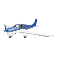
Nose Gear Centering
Factory settings for the nose gear steering trim should be close; observe the
following steps to fi ne tune the nose gear trim.
1. With the radio control system powered on, the rudder centered, and the rudder
trim centered, check the nose gear trim is centered.
2. To make adjustments, remove the servo hatch on the bottom of the fuselage.
The hatch is held with two magnets in the front and a tab in the rear.
3. Fine-tune the nose gear trim at the rudder servo by loosening the set screw
on the adjustable servo to pushrod linkage (A) and sliding the pushrod to the
desired position.
4. Tighten the screw to lock the pushrod into position.
5. Re-install the servo hatch.
8
Cirrus SR22T
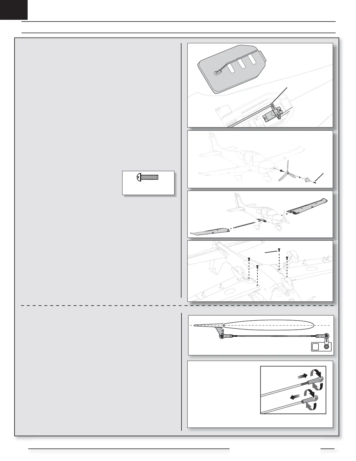
Control Surface Centering
After assembly and transmitter setup, confi rm that the control surfaces are
centered. If the control surfaces are not centered, mechanically center the control
surfaces by adjusting the linkages.
If adjustment is required, turn the ball link on the linkage to change the length of
the linkage between the servo arm and the control horn.
After binding a transmitter to the aircraft receiver, set the trims and sub-trims to
0, then adjust the ball links to center the control surfaces.
• Turn the linkage
clockwise or
counterclockwise until
the control surface is
centered.
• Attach the linkage
to the servo arm or
control horn after
adjustment.
 Loading...