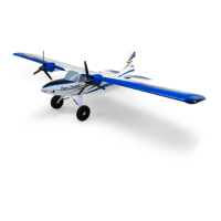
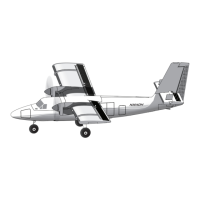
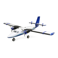
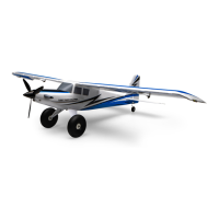
The Tower Hobbies DHC-2 Beaver 1.5m is a sophisticated hobby product, an RC (Radio Control) model aircraft designed for sport, recreation, education, and/or competition. It's a scale-like, STOL (Short TakeOff and Landing) craft that can be assembled with either conventional landing gear or included floats, allowing for flight from land or water.
Function Description
The DHC-2 Beaver 1.5m is a remote-controlled aircraft that allows users to experience the thrill of flying a scale model of the iconic DHC-2 Beaver. It's designed for both experienced pilots and those looking to develop their skills, offering a balance of stability and maneuverability. The model is controlled via a 6+ channel transmitter and receiver (not included), which operate various servos for control surfaces (elevator, ailerons, rudder, flaps) and the motor for propulsion. The aircraft features a lighting system for added realism.
Important Technical Specifications
- Wingspan: 59.5 inches (1510mm)
- Length: 38.5 inches (980mm)
- Flying Weight: 1360-1470g
- Motor: 4011-850Kv (TOWA137516)
- ESC (Electronic Speed Control): 40A, EC3 (TOWA137517)
- Servos: Five 9g Sub-Micro (TOWA137519)
- Propeller: 12 x 6 (TOWA137508)
- Transmitter: 6+ Channel (not included)
- Receiver: Spektrum™ AR637T (SPMAR637T) recommended (not included)
- Battery: 2200mAh 3S 11.1V 30C (SPMX22003S30, not included)
- Construction Material: Injection-molded EPO (expanded polyolefin) foam.
Usage Features
Assembly:
The model offers two main assembly configurations: conventional landing gear or floats.
- Landing Gear Installation: Involves fastening main landing gears to the fuselage with M3x16 screws and mounting the tail gear with M2.5x8 screws, ensuring the tail wheel is perpendicular to the steering arm.
- Floats Installation: Connects floats with horizontal struts using M2.5x20 screws and fastens braces to the floats with M2.5x8 screws, matching labels. Float braces are then secured to the fuselage with M3x16 and M2.5x8 screws. Water rudders are connected with rubber bands and rudder lines are fastened to the steering arm, with tension adjusted to center the rudders.
- Horizontal Stabilizer Installation: Fins are fastened to the horizontal stabilizer (stab) with M2x6 screws. The elevator pushrod connects to the bottom hole of the elevator horn. The stab is then rotated and keyed into the fuselage.
- Vertical Stabilizer Installation: The rudder torque rod is keyed into its receptacle, and the vertical stabilizer (fin) is fitted into the fuselage, then pressed into position. Both stabilizers are secured with an M3x22 screw.
- Wing Installation: Wing clips are fastened to the fuselage with M3x10 screws. Wires from the right wing are guided into the fuselage, and the wing joiner tube and flap pushrod wire are slid through corresponding holes. The flap pushrod wire is guided into the screw-lock connector on the flap servo. The joiner tube is guided through the left side of the fuselage, and the wing is clicked onto the wing clips. The left wing is mounted similarly. Wing struts are mounted to the wing with M2.5x8 screws and to the fuselage with M3x16 screws (over the third float strut or main landing gear).
- Receiver Installation: The receiver is installed on the right side of the front fuselage compartment, opposite the ESC, with servos connected according to wire labels.
- Battery Installation: The flight battery is installed in the angled middle section of the front fuselage compartment and secured with adhesive hook and loop material. Strips of hook-side material are applied inside the fuselage, and a loop-side strip is attached to the battery.
- ESC Operation: The throttle stick is moved to the lowest position, and the battery is connected to the ESC. The motor emits tones indicating startup, battery cell count, and arming.
- Control Surface Connection (Rudder and Elevator): The transmitter is powered on, throttle stick lowered, and trims centered. The battery is connected to the ESC. A magnetic screwdriver is recommended for removing and reinstalling screws on servo arms. The screw from the elevator servo arm connector is removed, threads are lightly wetted with threadlocker, and the screw is reinstalled (not tightened yet). With the transmitter and receiver on, the elevator is centered, and the screw is tightened. The same procedure is repeated for the rudder.
- Lights, Flaps, and Ailerons Connection: Wing lighting wires and aileron servo wires are connected to the lighting aileron and flap wiring harnesses from the receiver. The transmitter is turned on, the battery installed and connected, and the hatch secured.
- Flap Adjustment: The flap control dial/switch on the transmitter is moved to the "up" position. The screw in the flap servo arm is removed, threads wetted with threadlocker, and the screw reinstalled and tightened to ensure flaps are fully retracted.
- Aileron Adjustment: With the system on, ailerons are centered and aligned with wing tips. Aileron trim is adjusted if necessary. For significant adjustments, a small screwdriver can be used to pop off servo covers and adjust pushrods in the connectors.
Control Throws:
Control throws are factory installed but should be confirmed.
- Verify controls respond correctly to transmitter inputs; use servo reversing if needed.
- If using landing gear, prop up the fuselage to level wings and stab.
- Measure and set control throws at the widest part of each surface according to the recommended values:
- Elevator: High Rate (Up 11mm, Down 11mm), Low Rate (Up 8mm, Down 8mm)
- Ailerons: High Rate (Up 13mm, Down 13mm), Low Rate (Up 10mm, Down 10mm)
- Rudder: High Rate (32mm, 32mm), Low Rate (22mm, 22mm)
- Flap: 11mm
Adjust throws using transmitter programming or by relocating pushrod connectors on servo arms (inward for less throw, outward for more).
Propeller and Spinner Installation:
- Secure the backplate, propeller, washer, and nut to the aircraft.
- Tighten the two Phillips head screws to the spinner.
Safety Precautions: Always wear safety glasses, avoid operating in loose gravel/sand, keep spectators and body parts out of the propeller's rotation plane, never connect the battery indoors with the propeller installed, always remove the propeller when testing/repairing, stay behind the propeller arc, assume the motor may start unexpectedly, and keep loose clothing/hair/objects away from the propeller.
Center Of Gravity (CG):
Proper CG is crucial for stable flight.
- Mark forward and aft CG limits (2 and 2-1/2 inches or 51mm and 64mm back from the leading edge) on the bottom of the wing.
- Install the battery, battery hatch, cabin hatch, floats/wheels, and propeller.
- Lift the model by fingers between the marked lines. If balanced, it should sit level. If out of balance, add stick-on lead to the nose or tail.
Before Every Flight:
- Ensure all screws, servo arms, horns, and wing are secure.
- Install the recommended battery, adjusting placement for correct CG.
- Ensure flight battery and transmitter battery are fully charged.
- Ensure transmitter throttle stick is at the lowest position before powering on.
- Perform a control surface check after powering on.
- Check propeller rotation (with body parts clear).
- Inexperienced pilots should seek assistance.
Flying Tips:
- Always power on the transmitter before plugging in the battery.
- The aircraft flies similarly to other high-wing airplanes but with a slightly slower roll rate, suitable for its STOL nature.
- Flying With Flaps: Extending flaps too soon can cause the nose to pitch up. Gradually extend flaps or mix down elevator with flaps. Be prepared to counter nose pitch-up when powering up with flaps extended.
- Flying From Water: The Beaver handles well on water, even rough conditions. Water rudders are effective for steering, especially at idle speeds. Takeoffs can be long or short/steep. Avoid turning directly across high winds to prevent flipping. Floats slightly reduce air speed.
- Power Consumption: Normal flying (half-throttle cruising, full-throttle when needed) consumes about 200mAh/minute, yielding about 7 minutes with an 1800mAh battery and 8.5 minutes with a 2100mAh battery. Aggressive flying increases consumption to 260mAh/minute, reducing flight times to 5.5 minutes (1800mAh) and 6.5 minutes (2100mAh).
- Flight Timer: Set a conservative 5-minute timer. After landing, check battery capacity used to avoid over-discharging (use only 80% of capacity). Adjust flight time accordingly.
- Always unplug the battery from the plane before turning off the transmitter.
- Use a LiPo battery checker (HCAP0275) before and after flights to ensure proper charge levels.
- Have a flight plan in mind to improve skills and avoid impulsive maneuvers.
Maintenance Features
Repairs:
- Damaged parts can be purchased separately.
- The Beaver is made from EPO foam, which can be glued with regular CA (cyanoacrylate) without clamping. Softer, more flexible adhesives like white glue or canopy glue can also be used but require clamps or tape.
Electronic Speed Control Calibration:
- CAUTION: Remove the spinner and propeller before calibration to prevent injury from accidental motor startup.
- IMPORTANT: Calibrate throttle range due to varying transmitter throttle ranges.
- To set throttle range:
- Move throttle stick to the highest position.
- Connect battery to the ESC. The motor emits tones indicating startup, battery cell count, and highest throttle range recognition.
- Move throttle stick to the lowest position within 2 seconds. The ESC recognizes the low throttle position and arms.
Troubleshooting:
The manual provides a comprehensive troubleshooting guide for common issues:
- Aircraft not responding to throttle: Check if ESC is armed, throttle channel is reversed.
- Extra propeller noise/vibration: Check for damaged spinner/propeller/motor/mount, loose propeller/spinner parts.
- Reduced flight time/underpowered aircraft: Check for propeller installed backwards, low flight battery charge, damaged propeller/battery.
- Control surface not moving/slow response: Check for damaged control surface/horn/linkage/servo, loose wiring/connections.
- Controls reversed: Check transmitter channel reversing.
- Motor loses power/pulses: Check for motor/battery damage, ESC soft Low Voltage Cutoff (LVC).
- LED on receiver flashes slowly: Check for power loss to receiver, servo damage, linkage binding.
This detailed manual ensures users have all the necessary information for safe assembly, operation, and maintenance of their Tower Hobbies DHC-2 Beaver 1.5m.