Mounting
The Electronic 7 should be removed from the mounting box by unscrewing the 2
captive screws securing the
unit.
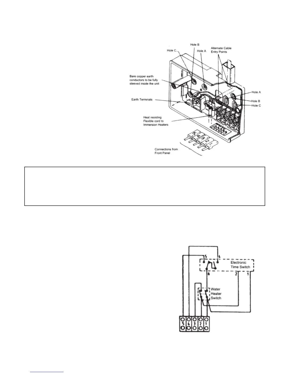
Conduit Box Mounting
Use either holes marked 'A' in
Fig.1 to secure to a single gang
box, or the two holes marked
'C' for a double gang box.
Cable entry is through the cut-
out between the 2 fixing holes
'A'.
Surface Mounting
Use the two holes marked 'B' in
Fig. 1 Cable entry is through
the most appropriate cut-out
REMOVE THE APPROPRIATE CABLE ENTRY CUT-OUTS BEFORE FIXING THE
BOX, WHERE POSSIBLE DRILL THE BOX TO PROVIDE A CLOSE FITTING
ENTRY FOR CABLES AND HEAT-RESISTANT FLEXIBLE CORDS. TAKE CARE TO
REMOVE SHARP EDGES .
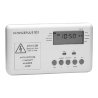
Connections
Use a three-core cable with a minimum
conductor size of 1.0mm for a 2kW heater, or
1.5mm for a 3kW heater to connect the unit to
the supply. Connect the incoming wires to the
terminal block as follows;
TERMINAL 1 - LIVE in
TERMINAL 2 - NEUTRAL in
TERMINAL 3 - NEUTRAL(s) out to immersion
heater(s)
TERMINAL 4 - LIVE out to Boost immersion
heater
TERMINAL 5 - LIVE out to Off-Peak immersion
heater
Clamp all surface wiring adjacent to the box or
use trunking where appropriate. Secure the
heat resistant flexible cords from the immersion
heaters using the cable clamp in the box.
Link terminals 4 & 5 when using
a single immersion heater
2