19
Maintenance
Step 2 Remove wand assembly from spray gun and
put spray gun into float tank. Secure the
trigger on the spray gun into the open
position.
Step 3 Turn engine on, allowing solution to be
pumped through coils back into the float
tank. The solution should be allowed to
circulate 2-4 hours or until the color changes.
Step 4 After circulating solution, flush the entire sys-
tem with fresh water. Clean out float tank and
then reinstall wand assembly to spray gun.
Removal of Soot from Heating Coil
In the heating process, fuel residue in the form of soot
deposits may develop between the heating coil pipes,
and block air flow which will affect burner combustion.
When soot has been detected on visual observation,
the soot on the coil must be washed off after following
the coil removal steps (See Coil Removal).
Relief Valve
WARNING: The relief valve on this pressure washer
has been factory set and sealed and is a non-field
adjustable part. Tampering with the factory setting
may cause personal injury and/or property damage
and will void the manufacturer warranty. For
replacement parts refer to coil outlet assembly
exploded views.
AVERTISSEMENT: La soupape de décharge sur
cette laveuse à pression a été réglée en usine, puis
scellée, et est une pièce non réglable. L'altération
du paramètre de l'usine pourrait causer des lésions
corporelles et/ou des dommages à la propriété, et
annulera la garantie du fabricant. Pour des pièces
de rechange, se référer aux vues éclatées.
Fuel
Use clean fuel oil that is not contaminated with water
and debris. Replace fuel filter and drain the tank every
100 hours of operation.
Use diesel fuels specified to (ASTM D975) grade #1 or
#2 only. NEVER use gasoline in your fuel tank.
Gasoline is more combustible than fuel oil and could
result in a serious explosion. NEVER use crankcase or
waste oil in your burner. Fuel unit malfunction could
result from contamination.
NOTE: See Kubota engine manual for fuel
recommendations.
Fuel Control System
This machine utilizes a fuel solenoid valve located on
the fuel pump to control the flow of fuel to the
combustion chamber. The solenoid, which is normally
closed, is activated by a pressure switch when pump is
under load. When the operator releases the trigger on
the spray gun, the pump goes into by-pass relieving
pressure on the pressure switch turning off the elec-
trical current to the fuel solenoid.
The solenoid then closes, shutting off the supply of fuel
to the combustion chamber. Controlling the flow of fuel
in this way gives an instantaneous burn-or-no-burn
situation, thereby eliminating high and low water
temperatures and the combustion smoke normally
associated with machines incorporating a spray gun.
Periodic inspection, to insure that the fuel solenoid
valve functions properly, is recommended. This can be
done by operating the machine and checking to see
that the burner is not firing when the spray gun is in the
OFF position.
Fuel Pressure Adjustment
Fuel pressure is factory set to the serial plate. Adjust
fuel pressure by turning the regulating pressure
adjusting screw clockwise to increase, counterclock-
wise to decrease. Do not exceed 200 psi. NOTE: When
changing fuel pump, a bypass plug must be installed in
return port or fuel pump will not prime.
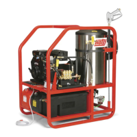
Gun Setting Instructions (Wayne EH)
Suggested start-up setting: EH flameblock™ 1/8"
ahead of cast iron cone face for 3.00 to 4.00 GPH or
1/4" ahead for 5.00 to 6.00G PH.
Left Hand
Electrode
Cast Iron
Air Cone
Nozzle
1/8”
5/16”
1/8”
Right Hand
Electrode
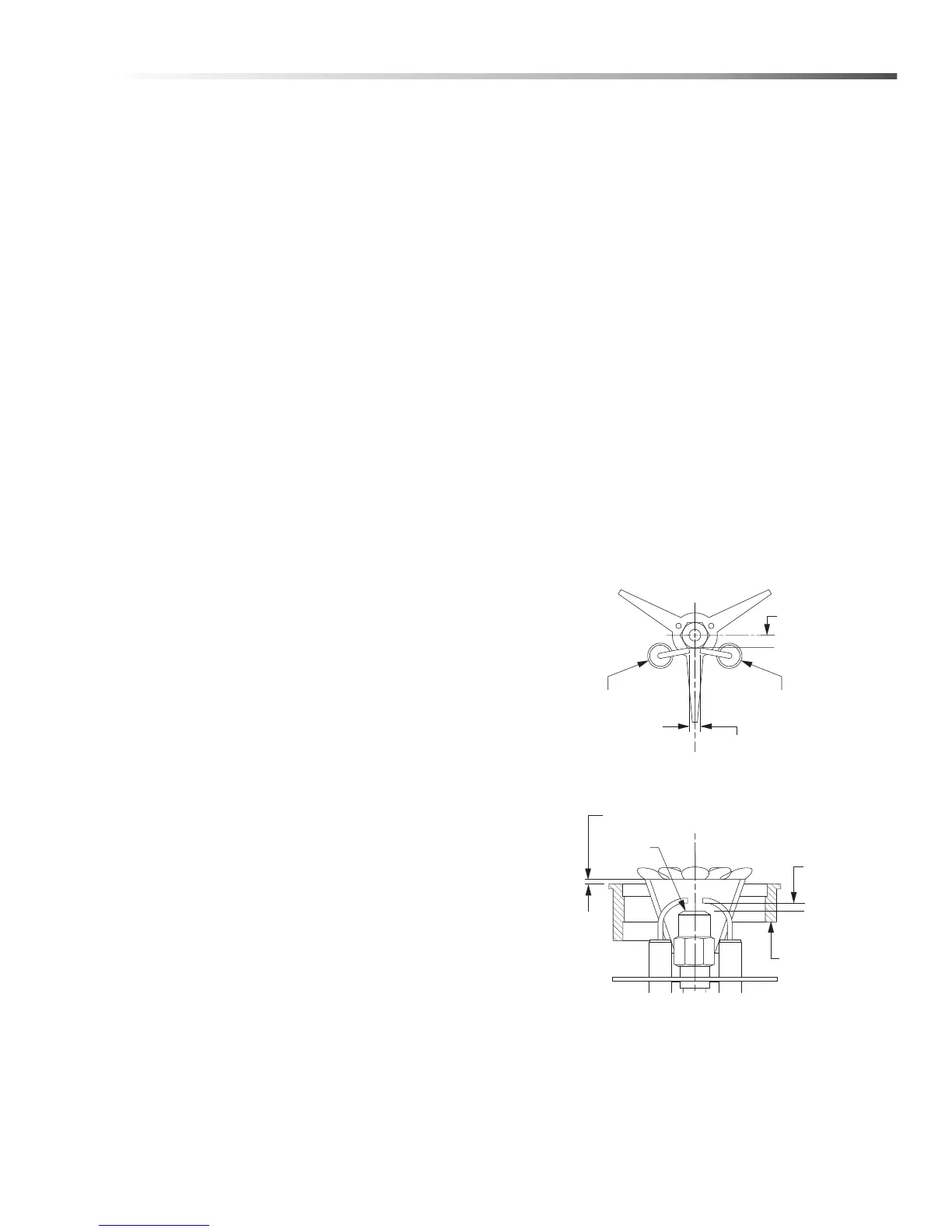
Reference Gun Settings
ELECTRODE SETTINGS
Periodically Check Wiring Connections.
If Necessary to adjust electrodes, use diagram.
Manual Operator HOTSY 1265SSD/S 9.808-057.0 - A