Do you have a question about the Hotsy 952SS-208 and is the answer not in the manual?
Details the responsibilities of the owner and user for understanding and following operating instructions and warnings.
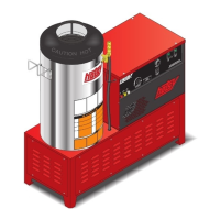
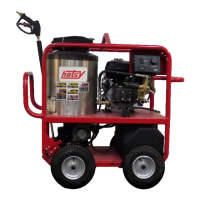
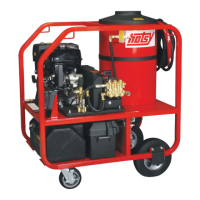
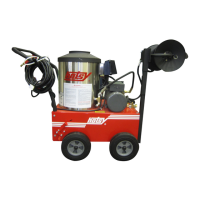
Identifies and labels the main components of the Hotsy pressure washer system for user reference.
Provides instructions for unpacking the pressure washer and assembling basic components like the hose and wand.
Guidelines for positioning the pressure washer on a level, protected surface for optimal performance and access.
Details necessary venting procedures for exhaust fumes to ensure safe operation and prevent hazards.
Instructions for connecting the water supply and natural gas fuel, including pressure requirements.
Information on gas valve settings, incoming pressure, and essential electrical grounding and connection requirements.
Pre-operation checks including reading manuals, inspecting hoses, checking fluid levels, and nozzle installation.
Step-by-step guide on how to safely start the pressure washer, including bleeding air and igniting the burner.
Instructions on applying detergent, selecting nozzles, and proper washing techniques for effective cleaning.
Procedure for safely shutting down the machine, including purging detergent and cooling the coil.
Guidance on protecting the machine from freezing and preparing it for long-term storage with antifreeze.
Recommendations for pump oil, proper pump care, and motor lubrication to ensure longevity.
Advice on servicing the gas burner, descaling, and desooting the heating coil for optimal performance.
Information regarding the relief valve and unloader valve, emphasizing factory settings and avoiding tampering.
A guide to diagnosing and resolving common operational issues with the pressure washer.
A diagram illustrating the overall assembly of the pressure washer with numbered components.
A detailed list of part numbers, descriptions, and quantities for the main components of the machine.
An exploded view illustrating the components of the burner assembly.
A list of part numbers and descriptions for components specific to the burner assembly.
An exploded view showing the components of the pump assembly.
A list of part numbers and descriptions for components of the pump assembly.
An exploded view of the float tank assembly, showing its constituent parts.
A list of part numbers and descriptions for the float tank assembly components.
An exploded view illustrating the components of the control panel.
A list of part numbers and descriptions for the control panel components.
Detailed exploded view of the pump assembly showing internal components.
A comprehensive list of part numbers and descriptions for the pump assembly.
Parts list for the high-pressure hose and trigger gun assembly, including various nozzles.
Detailed parts list for the trigger gun assembly, including internal components and repair kits.
A table detailing various specifications and part numbers for different pressure washer models.
Wiring diagram for 3-phase models with electric ignition, illustrating electrical connections.
Wiring diagram for 3-phase models with electric ignition and thermal shutdown features.
Wiring diagram for 3-phase models with electric ignition and auto start functionality.
Wiring diagram for 1-phase models with electric ignition, detailing electrical connections.
Wiring diagram for 1-phase models with electric ignition and thermal shutdown.
Wiring diagram for 1-phase models with electric ignition and auto start features.
Details the one-year limited warranty covering defects in material and workmanship under normal use.
Lists specific parts like pumps, manifolds, and heating coils with extended warranty periods.
Outlines limitations of Hotsy's liability for damages and clarifies the purpose of product illustrations.
Addresses compliance with local codes and procedures for handling defective products.
| Brand | Hotsy |
|---|---|
| Model | 952SS-208 |
| Category | Pressure Washer |
| Language | English |