5
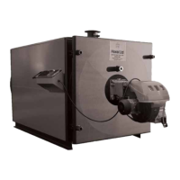
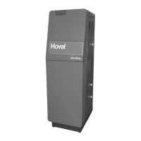
Description of the SR-plus boiler
Description of the SR-plus boiler
Applications
These boilers are intended for heating commercial and
industrial premises within the limits of temperature and
pressure stated in this manual. They may also be used
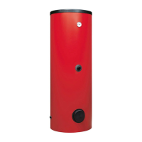
to supply D.H.W. to such premises in conjunction with
an indirect calorier.
Benets & Features
• UK design & manufacture
• W h e r e a p p l i c a b l e f u l l c o m p l i a n c e w i t h t h e P r e s s u r e
Equipment Regulations.
• no minimum ow rate
• compact, space saving design
• standing losses less than 0.4%
• nett efciency to 91.6%
• suitable for operation with a range of
matched burners for use with oil, gas or dual fuel
General Details
The boilers are of mild steel welded construction in
which the outer shell forms a water space around the
combustion chamber.
The third pass water jacketed gas passage ways with
turbulators provide an effective secondary heating
surface. Flue gases pass to a rear mounted ue outlet
box and horizontal ue outlet. The ue outlet has a
spigot/ange for connecting to the installers ue pipe,
and is tted with a door for cleaning and access.
The SR-plus is tested and manufactured to European
boiler design codes and is offered in outputs from
500 to 4150KW. The boilers are suitable for working
pressures up to 6 bar and operating temperatures to
a maximum of 100 °C.
General
The maximum operating temperature is governed
by the pressure available at the highest point of the
system. Take the 17
o
C anti-ash margin from the
saturated temperature of steam at that pressure to nd
the maximum operating temperature.
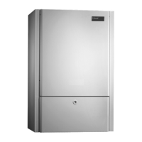
Door Hinging
The hinged side door nuts are supplied with a locknut
at the back of the door boss. Hoval should be advised
of the door and gas burner handing when the boiler is
ordered or at the very earliest date.
For installation space requirements and for changing
door hinging see page 9.
On request
- ue gas thermometer
- separately mounted altitude gauge
- boiler door hinged on left hand side
- volt free contacts for B.M.S.
- hours run meter
- Modulating controller
Insulation / Cladding
100mm mineral bre wrap with woven aluminium
surface around boiler shell, complete with Hoval red
cladding panels.
Electrical Power Supply
A single phase 230V supply is required for the control panel operation. Single phase burners are electrically
supplied via the control panel. Three phase burners require a separate three phase isolated supply (by the
installer) direct to the burner, incorporating a exible connection to allow for boiler/burner door opening. In
this case control cables tted with wieland plug/socket will still run between the control panel and the burner.
All power supplies to the boiler/burner/other associated equipment (ie: gas booster, separate oil pump, etc.)
should be isolated via the same switched isolator.
Operation
Normal operation is fully automatic in conjuction with a
simple time switch or other form of control i.e. BEMS