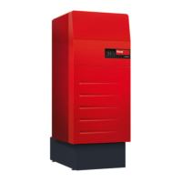
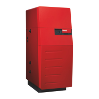
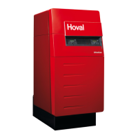
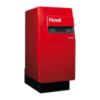
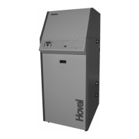
3.3 Mounting the casing
1. Attach the cable channels (2) left and right to the pins and fix with the hexagon nuts and
washers (3a, fig. 4a) already mounted to the boiler. Turn side wall supports (2b, fig. 4b) laterally
to the outside.
2. Attach the side walls (4) to the boiler and fix with the hexagon nuts and washers (4a, fig. 4a) al-
ready mounted to the boiler. Hook the side wall side onto the screw head on the condensate drip
tray at the bottom. Align the side walls centrally. Adjust the free space for electrical box and rear
wall. Then tighten the hexagon nuts (4a).
3. Fit the rear wall (terminal plate 5, fig. 4c) of the terminal box using 4 screws (4a).
4. Remove stud (6) on the left or right. Hook the terminal box in at the bottom, on the side where the
stud is located. Hold the terminal box in horizontal position and tighten in position with the second
stud on the opposite side.Fold the terminal box shut towards the top and hook it in.
5. Fit the trim (7)
- in order to insert the upper screw (7a). Open the terminal box
- in order to insert the lower screw (7b). Close the terminal box
6. Direct the cable for the water pressure sensor (7) downwards, out of the control and plug in at
the bottom of the boiler (cable run according to fig. 4).
Route all other cables to the left or right of the boiler and establish plug connections.
Make sure that the cable does not touch any hot locations!
7. Attach the lower rear wall (8) to the side walls. Mutually attach the rear walls (8a, 8b) and engage
together at the side walls.
8. Fit top side walls (9a, 9b). Position the lower edge of the top side walls (longitudinal bore hole) on
the special screws of the bottom side walls and slide them in. Attach top side walls using 4 self-
tapping screws (9c) ø 3.5 x 10.
9. Attach upper rear walls (10, fig. 4) and mount rosette (10a).
10. Put on cover plates (11). Fit top front cover (11a), place pins in slots and slide towards the rear.
Then secure with carriage bolt (11b, fig. 4). (When removing, lift first one side, then the other side).
11. Hook in the front cover (8) at the bottom (with rail from type 575) and slide shut at the top (attach
with lateral carriage bolt). In the case of a cascade >3, no carriage bolts are fitted on the middle
boilers!
12. The remaining 3 casing walls (15, 15a, 16, fig. 6) are attached after mounting the condensate
boxes.
 Loading...