12
Motor
Manual
7 Motor data and parts
7.1 Exploded view of motor and cross-section
view
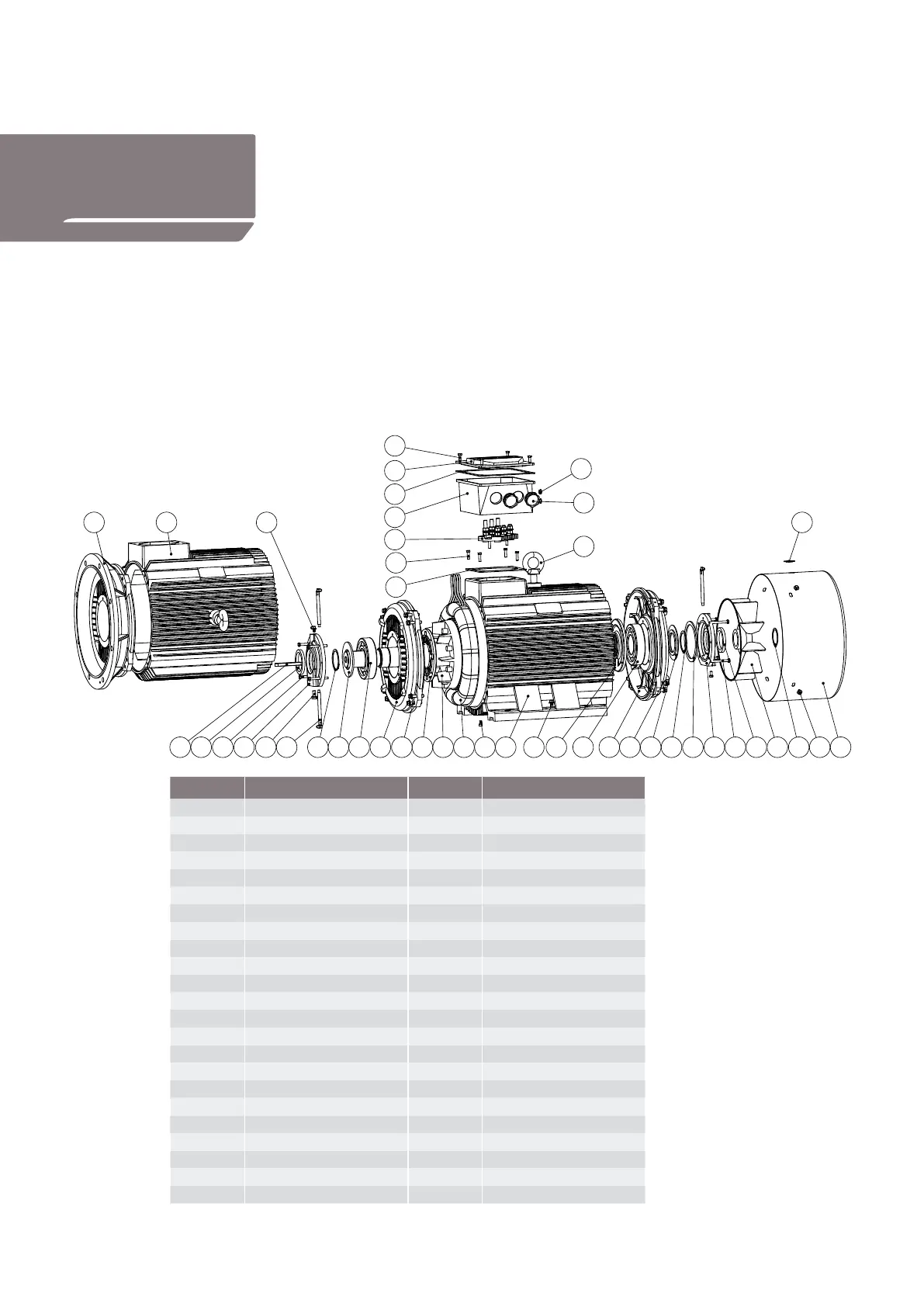
Figure 2 below shows an exploded view of a cast iron motor.
Figure 3 shows a cross-section view of an aluminium motor.
Figure 2 Exploded view
of a cast iron motor
Item No. Part name Item No. Part name
1 Key 24 Spring wave washer
2 Sealing ring_De 25 Outer bearing cap_NDE
3 Bolt 26 Bolt
4 Outer bearing cap_DE 27 Sealing ring_NDE
5 Bolt & O-ring 28 Cooling fan
6 Grease pipe 29 Circlip
7 Circlip 30 Bolt & Washer
8 Oil slinger 31 Fan cover
9 Bearing_DE 32 Rubber plug
10 B3 and shield_DE 33 Eye bolt
11 Bolt & Washer 34 Bolt
12 Inner bearing cap_DE 35 Terminal box cover
13 Rotor with shaft 36 Gasket
14 Winding stator 37 Terminal box base
15 Bolt & O-ring 38 Blind cap
16 B3 housing 39 Cable gland
17 Bolt & Washer 40 Terminal board
18 Inner bearing cap_NDE 41 Bolt
19 Bearing_NDE 42 Gasket
20 B3 end shield_NDE 43 Grease nipple
21 Bolt & Washer 44 B5 housing
22 Oil slinger 45 B5 flange
23 Circlip
Over Hadstenvej 42, DK-8370 Hadsten
Tel : +45 86982111
Fax: +45 86981779
www.hoyermotors.com
Hoyer Motors
DRAWN
31312
01
kg
BREAK SHARP
HMC2-315-exploded_V02
Motors and for no other purpose.
SHEET 1 OF 1
WEIGHT:
CI
TIH
A3
SCALE:1:50
DWG NO.
TITLE:
CHK'D
APPV'D
REVISION
DO NOT SCALE DR AWING
MATERIAL:
DATESIGNATURE
NAME
EDGES
Q.A
MFG
DEBUR AND
© 2010 Hoyer Motors All intellectual property rights and all rights in know-how in relation to this drawing may not be reproduced, stored, or transmitted in any form by any means (electronic, mechanical,photocopying, recording or otherwise) without the prior written consent of Hoyer Motors. It is to be used only for the purposes specified by Hoyer
20190711
34
10
41
42
4445 43
1 2 3 54 7 8 9 126 13 1511
40
16 17 18 19 2120 22 23 24 25 26 27 31
32
28 29 30
33
35
36
37
39
38
14
Item No. Part name Item No. Part Name
1 Key 24 Spring wave washer
2 Sealing ring_DE 25 Outer bearing cap_NDE
3 Bolt 26 Bolt
4 Outer bearing cap_DE 27 Sealing ring_NDE
5 Bolt&O-ring 28 Cooling fan
6 Grease pipe 29 Circlip
7 Circlip 30 Bolt&Washer
8 Oil slinger 31 Fan cover
9 Bearing_DE 32 Rubber plug
10 B3 end shield_DE 33 Eye bolt
11 Bolt&Washer 34 Bolt
12 Inner bearing cap_DE 35 Terminal box cover
13 Rotor with shaft 36 Gaket
14 Winding stator 37 Terminal box base
15 Bolt&O-ring 38 Blind cap
16 B3 housing 39 Cable gland
17 Bolt&Washer 40 Terminal board
18 Inner bearing cap_NDE 41 Bolt
19 Bearing_NDE 42 Gasket
20 B3 end shield_NDE 43 Grease nipple
21 Bolt&Washer 44 B5 housing
22 Oil slinger 45 B5 flange
23 Circlip
Note that the bearing retainer plate is secured on the inside
at the drive end.