Do you have a question about the Hoymiles HM-800 and is the answer not in the manual?
Lists the specific Hoymiles Microinverter models this manual covers.
Identifies the manual's intended audience as qualified technicians with training.
Explains the meaning of safety symbols like Danger, Warning, and Caution used in the manual.
Provides essential safety precautions for the installation and operation of the microinverter.
Explains the meaning of specific safety symbols, including waste disposal and high voltage warnings.
Discusses potential radio interference and provides steps to mitigate it.
Introduces the unique "2 in 1 Unit" design of the microinverter for PV systems.
Summarizes the key features and advantages, such as maximum output power and reliability.
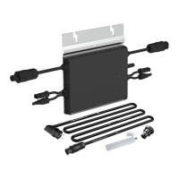
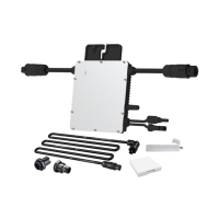
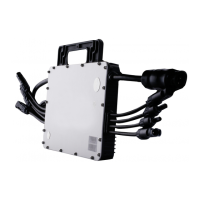
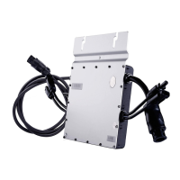
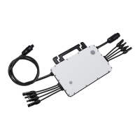
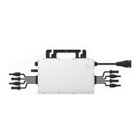
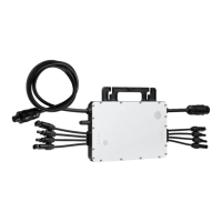
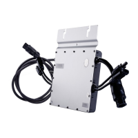
Identifies and describes the AC and DC connectors on the microinverter unit.
Provides the physical dimensions of the microinverter in millimeters.
Explains the different operational modes: Normal, Zero Export Control, and Standby.
Lists and describes the accessories needed for microinverter installation.
Outlines precautions to take before and during the installation process.
Details the required spacing and clearance for optimal installation and performance.
Covers essential preparation steps, environmental checks, and site considerations.
Details the first step of physically mounting the microinverter onto the rail.
Describes how to connect the AC cables between microinverters to form a circuit.
Explains the process of connecting the AC end cable to the circuit.
Details the procedure for creating an installation map using serial numbers.
Describes how to connect the DC cables from PV modules to the microinverter.
Explains the steps to safely energize the installed system.
Guides on setting up the monitoring system via DTU.
Lists common alarm codes, their names, and suggested troubleshooting steps.
Explains the status indications provided by the LED light on the microinverter.
Provides a step-by-step guide for qualified installers to troubleshoot inoperable microinverters.
Outlines procedures for routine maintenance and inspection of the microinverter.
Provides detailed instructions on how to remove and replace a microinverter unit.
Describes the process for disconnecting and removing the microinverter from the system.
Details proper methods for storing and transporting the microinverter components.
Provides guidelines for the environmentally sound disposal of the microinverter.
Explains the system's compliance with earth fault monitoring standards and indications.
Describes the power quality response modes supported by the inverter, like Volt-Watt.
Explains the Demand Response Modes (DRM) supported by the microinverter.
Lists the technical specifications for the DC input voltage, current, and power.
Lists the technical specifications for the AC output voltage, current, power, and frequency.
Provides data on peak and CEC weighted efficiency, and safety features.
Lists mechanical specifications like dimensions, weight, and temperature ranges.
Summarizes communication, monitoring, warranty, and compliance features.
Provides a template for recording installation details, including panel grouping and serial numbers.
Illustrates the wiring diagram for a 230VAC single-phase system connection.
Illustrates the wiring diagram for a 230VAC/400VAC three-phase system connection.
| Model | HM-800 |
|---|---|
| Category | Inverter |
| Max Output Power | 800 W |
| Input Voltage Range | 16 V - 60 V |
| Output Voltage | 230 V |
| Efficiency | 96.5% |
| Max. DC Input Voltage | 60 V |
| Start-up Voltage | 22 V |
| Max. Input Current | 12 A |
| Nominal Output Power | 800 W |
| Nominal Output Current | 3.48A |
| Nominal Output Voltage/Range | 230 V |
| Enclosure Rating | IP67 |
| Number of MPPT Trackers | 2 |
| AC Output Frequency | 50 Hz / 60 Hz |
| Cooling Method | Natural Convection |
| MPPT Voltage Range | 16V-60V |
| Ambient Temperature Range | -40°C to +65°C |
| Operating Temperature Range | -40 ~ +65°C |