EasyManua.ls Logo

Hoymiles HM-800 Series - User Manual

Hoymiles HM-800 Series
2 pages
Print Icon
To Next Page IconTo Next Page
Loading...
A
B
C
D
01
Region: Global AP040209 REV1.4 © 2022 Hoymiles Power Electronics Inc. All rights reserved.
1. Accessories
*Note: Please install the microinverter at least 50 cm above the ground/roof for better communication with the Hoymiles DTU.
Step 2. Connect AC Cables of Microinverter
Item Description
AC End Cable (Female), 2 m 12 AWG Cable
M8 × 25 Screws
DC Extension Cable, 1 m
AC Female End Cap, IP67
A) Plug the AC connector of the first
microinverter into the connector of the
second microinverter to form a
continuous AC branch circuit.
B) Install the AC end cap on the open AC
connector of the last microinverter in
the AC branch circuit.
*Note: All accessories listed above are not included in the package, and need to be purchased separately. Please contact our sales representative
for pricing information. (M8 screws need to be prepared by the installer.)
2. Installation Steps
Ensure the microinverter is installed in the required environment. (Refer to product user manual for more details.)
Step 1. Attach Microinverter on Rail
A) Mark the approximate center of each panel on the frame.
HM-800 Series Quick Installation Guide
B) Fix the screw on the rail.
C) Hang the microinverter on the screw (as
shown in the picture), and tighten the
screw. The silver cover side of the
microinverter should be facing the panel.
*Note: The length of AC cable on
microinverter is around 2.04 m. Use AC
extension cable if two microinverters are
more than 2.04 m apart.
*Applicable to HM-600/700/800 microinverters
Question and Answer IconNeed help?

Do you have a question about the Hoymiles HM-800 Series and is the answer not in the manual?

Summary

Accessories

Installation Steps

Attach Microinverter on Rail

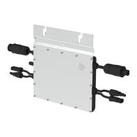
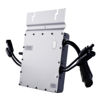
Attaching the microinverter onto the mounting rail using screws for secure installation.

Connect AC Cables of Microinverter

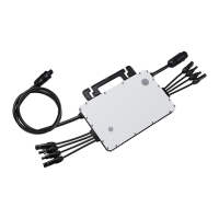
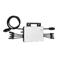
Linking microinverters using AC connectors to form a continuous AC branch circuit.

Connect AC End Cable

Wiring and connecting the AC end cable to the distribution box and local grid network.

Create an Installation Map

Peeling serial number labels from microinverters and affixing them to an installation map.

Connect PV Modules

Mounting PV modules and connecting their DC cables to the microinverter's DC input.

Energize the System

Turning on AC breakers to energize the system and initiate power generation.

Set Up the Monitoring System

Installing the DTU and setting up the monitoring system via the Hoymiles Cloud platform.

Overview

This document outlines the installation and setup procedures for the Hoymiles HM-800 Series microinverters, which are also applicable to the HM-600 and HM-700 models. It serves as a quick installation guide, providing step-by-step instructions for connecting the microinverters, AC cables, and PV modules, as well as setting up the monitoring system.

Function Description

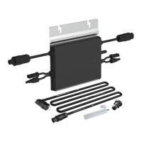
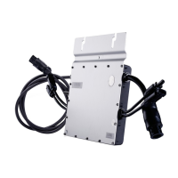
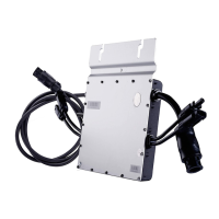
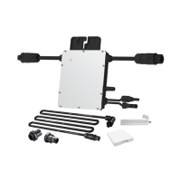
The Hoymiles HM-800 Series microinverters are designed to convert direct current (DC) generated by photovoltaic (PV) modules into alternating current (AC) for use in residential or commercial power grids. Each microinverter is typically connected to one or more PV modules, allowing for independent power optimization and monitoring of individual modules. This distributed architecture enhances system reliability and energy harvest by mitigating the impact of shading or module performance variations. The system includes various accessories for secure and efficient electrical connections, such as AC end cables, screws, DC extension cables, and AC end caps. The overall system is designed for ease of installation and integration with a monitoring system (S-Miles Cloud via a DTU) to track performance.

Usage Features

The installation process is broken down into several key steps, ensuring a systematic approach to setting up the microinverter system.

1. Accessories: The guide lists essential accessories required for installation, including:

  • AC End Cable (Female), 2 m 12 AWG Cable: Used for connecting the microinverters to the AC branch circuit.
  • M8 x 25 Screws: For securely attaching the microinverters to the mounting rail.
  • DC Extension Cable, 1 m: Provides additional length for connecting PV modules to the microinverter if needed.
  • AC Female End Cap, IP67: Used to seal the open AC connector of the last microinverter in the branch circuit, ensuring weather protection. It's important to note that these accessories are typically not included in the package and must be purchased separately.

2. Installation Steps: The installation begins by ensuring the microinverter is placed in an appropriate environment, as detailed in the product user manual.

Step 1: Attach Microinverter on Rail:

  • A) Marking: The first step involves marking the approximate center of each PV panel on the mounting frame. This helps in correctly positioning the microinverters.
  • B) Fixing Screws: M8 x 25 screws are then fixed onto the rail at the marked positions.
  • C) Hanging and Tightening: The microinverter is hung onto these screws, with the silver cover facing the PV panel, and then securely tightened. A crucial note here is that the microinverter should be installed at least 50 cm above the ground or roof level to ensure optimal communication with the Hoymiles DTU (Data Transfer Unit).

Step 2: Connect AC Cables of Microinverter:

  • A) Continuous AC Branch Circuit: The AC connector of the first microinverter is plugged into the connector of the second microinverter, and so on, to form a continuous AC branch circuit. This daisy-chain connection simplifies wiring.
  • Note on AC Cable Length: The standard AC cable on the microinverter is approximately 2.04 meters long. If the distance between two microinverters exceeds this length, AC extension cables should be used to maintain the connection.
  • B) AC End Cap Installation: An AC end cap is installed on the open AC connector of the last microinverter in the branch circuit. This cap, with an IP67 rating, provides protection against dust and water ingress, ensuring the longevity and safety of the electrical connections.

Step 3: Connect AC End Cable: This step details the assembly and connection of the AC end cable, which links the microinverter string to the main electrical system.

  • A) Making the AC End Cable:
    • 1. Separation: The AC port is separated into three distinct parts for easier wiring.
    • 2. Wiring: The AC cable is threaded through Part 3 and Part 2, and then the L (Brown wire), N (Blue wire), and Ground (Yellow/Green wire) wires are connected inside Part 1. The guide specifies using a 12 AWG cable for the AC end cable.
    • 3. Assembly: Once the wiring is complete, Part 2 is plugged into Part 1, and Part 3 is screwed on to complete the AC extension cable assembly.
  • B) Connecting to First Microinverter: The assembled AC end cable is then connected to the AC male connector of the first microinverter in the branch circuit, completing the electrical path from the microinverters.
  • C) Connecting to Distribution Box: The other end of the AC end cable is connected to the distribution box and wired into the local grid network, integrating the solar power generation with the household or building's electrical system.

Step 4: Create an Installation Map: This step is crucial for system monitoring and maintenance.

  • A) Serial Number Label: Removable serial number labels are peeled from each microinverter. The guide indicates where these labels are located on the device.
  • B) Affixing Labels: These serial number labels are then affixed to the corresponding locations on an installation map. This map provides a visual representation of the microinverter layout and their unique identifiers, which is essential for tracking individual microinverter performance through the monitoring system.

Step 5: Connect PV Modules:

  • A) Mounting PV Modules: The PV modules are mounted directly above their respective microinverters.
  • B) Connecting DC Cables: The DC cables from the PV modules are connected to the DC input side of the microinverters. This establishes the DC electrical connection, allowing the microinverters to receive power from the solar panels.

Step 6: Energize the System:

  • A) AC Breaker (Branch Circuit): The AC breaker for the branch circuit (where the microinverters are connected) is turned on.
  • B) Main AC Breaker (House): The main AC breaker for the house is then turned on. After these steps, the system will typically begin generating power within approximately two minutes.

Step 7: Set Up the Monitoring System: This final step involves configuring the monitoring system to track the performance of the microinverters.

  • DTU and S-Miles Cloud: Users are directed to refer to the DTU User Manual, DTU Quick Installation Guide, and Quick Installation Guide for S-Miles Cloud. These documents provide detailed instructions for installing the DTU (Data Transfer Unit) and setting up the S-Miles Cloud monitoring system. The DTU collects data from the microinverters and transmits it to the cloud platform, allowing users to monitor energy production, identify potential issues, and manage their solar power system remotely.

Maintenance Features

While the guide primarily focuses on installation, several aspects contribute to the maintainability and long-term performance of the system:

  • IP67 Rated AC End Cap: The use of an IP67-rated AC female end cap ensures that the electrical connections are protected from environmental elements like dust and water. This reduces the risk of corrosion and electrical faults, minimizing the need for frequent repairs or replacements due to weather damage.
  • Installation Map with Serial Numbers: The creation of an installation map with each microinverter's serial number is a critical maintenance feature. In the event of a performance issue or fault with a specific microinverter, this map allows for quick identification of the affected unit, streamlining troubleshooting and replacement processes. Without this map, diagnosing issues in a multi-microinverter system would be significantly more challenging and time-consuming.
  • DTU and S-Miles Cloud Monitoring System: The monitoring system is a powerful tool for proactive maintenance. By continuously tracking the performance of individual microinverters and PV modules, the system can alert users to any anomalies or underperformance. This allows for early detection of potential issues, such as shading, module degradation, or microinverter malfunction, enabling timely intervention before they significantly impact energy production. Remote monitoring capabilities reduce the need for on-site inspections, saving time and resources.
  • Modular Design: The use of individual microinverters for each (or a small group of) PV modules inherently offers a maintenance advantage. If one microinverter fails, it typically does not affect the performance of other microinverters in the system. This modularity simplifies fault isolation and replacement, as only the faulty unit needs attention, rather than the entire string or system.
  • Clear Wiring Instructions: The detailed instructions for connecting AC and DC cables, including specifications for wire types (e.g., 12 AWG for AC end cable) and proper sealing with end caps, contribute to a robust and reliable electrical installation. A well-installed system is less prone to electrical failures, reducing maintenance requirements over its lifespan.
  • Minimum Clearance for DTU Communication: The recommendation to install microinverters at least 50 cm above the ground/roof for better communication with the DTU is a design consideration that supports reliable data transmission. Consistent communication is vital for effective monitoring and, by extension, for identifying and addressing maintenance needs promptly.

In summary, the Hoymiles HM-800 Series microinverter system is designed for straightforward installation and offers robust features that support long-term reliability and ease of maintenance through its modular architecture, protective components, and comprehensive monitoring capabilities.

Hoymiles HM-800 Series Specifications

General IconGeneral
Max DC Voltage60V
Power Factor>0.99
THD<3%
Cooling MethodNatural Convection
Input Voltage Range16-60V
MPPT Voltage Range16V-60V
Output Voltage230V
Frequency50Hz/60Hz
CommunicationWi-Fi
ModelHM-800

Related product manuals