Do you have a question about the Hoymiles HM-1200NT and is the answer not in the manual?
Lists the Hoymiles Microinverter models covered by this manual.
Specifies that the manual is intended for qualified technicians only.
Explains safety symbols such as Danger, Warning, and Caution.
General safety precautions for installation and operation of the microinverter.
Explains the WEEE symbol for waste electrical and electronic equipment.
Details FCC compliance and measures to reduce radio interference.
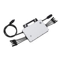
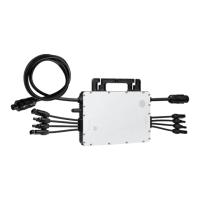
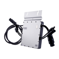
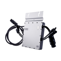
Introduces the "4 in 1 Unit Microinverter" and its key features.
Lists key features and specifications like peak output power and efficiency.
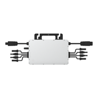
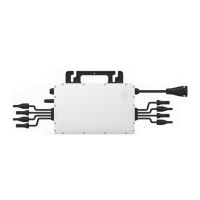
Identifies and describes the AC and DC connectors on the microinverter.
Provides the physical dimensions of the microinverter.
Explains the different operating modes: Normal, Zero Export Control, and Standby.
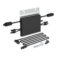
Lists and describes the accessories required for installation.
Advises on precautions for installing the microinverter and DC connections.
Specifies the necessary spacing for optimal communication and performance.
Outlines preparatory steps before installing the equipment.
Details steps for planning cable length and installing AC bus end caps.
Step-by-step guide on how to fix the microinverter onto the rail.
Instructions for connecting the AC bus cable and securing vacant ports.
Guide on preparing and connecting the AC end cable to the distribution box.
Process for creating an installation map using serial numbers.
Instructions for mounting PV modules and connecting DC cables.
Steps to turn on the AC breakers and energize the system.
Guidance on setting up the monitoring system using DTU documentation.
A comprehensive list of alarm codes, names, and suggested solutions.
Explains the meaning of different LED flash patterns for status indication.
Step-by-step guide for troubleshooting inoperable microinverters.
Guidelines for performing regular maintenance and safety precautions.
Detailed instructions on how to remove and replace a microinverter.
Steps for disconnecting and removing the microinverter from the frame.
Guidelines for safely storing and transporting the microinverter.
Instructions for proper disposal of the microinverter and packaging.
Table detailing DC input specifications for different models.
Table detailing AC output specifications for different models.
Table of efficiency ratings and safety parameters.
Table of mechanical specifications like dimensions and weight.
Lists key features such as communication, monitoring, and warranty.
Describes the grid support interactive inverter and its compliance.
Table showing measurement accuracy tolerances for Volts, Watts, VAr, etc.
Details voltage ride-through parameters and trip settings.
Details frequency ride-through parameters and trip settings.
Specifies ramp rate and soft start adjustment ranges and tolerances.
Table for specified power factor adjustment ranges.
Table for Volt/VAr parameters like output power and reactive power.
Table for Frequency-Watt parameters like output power and frequency droop.
Table for Volt-Watt parameters like output power and power reduction slope.