Do you have a question about the Hoymiles HM-1000 and is the answer not in the manual?
Lists the Hoymiles microinverter models covered in the manual.
Specifies that only trained technicians should install and maintain the microinverter.
Explains the meaning of safety symbols like Danger, Warning, and Caution.
Provides crucial safety instructions for installation, operation, and maintenance of the microinverter.
Details the meaning of various safety and compliance symbols used in the manual.
Addresses the microinverter's compliance with EMC standards and provides advice for potential radio interference.
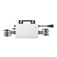
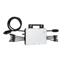
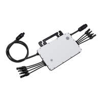
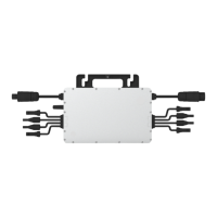
Introduces the 4-in-1 unit microinverter and its advantages.
Summarizes the key technical highlights and performance features of the microinverter.
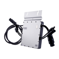
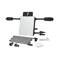
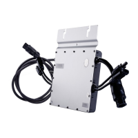
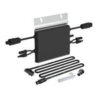
Identifies and describes the different connectors on the microinverter.
Provides the physical dimensions of the microinverter in millimeters.
Explains the different operating modes of the microinverter: Normal, Zero Export Control, and Standby.
Lists and describes accessories required for installation, some of which are sold separately.
Offers important precautions for installing the microinverter, including placement and ventilation.
Details the recommended space distance for installing microinverters, especially on roofs.
Explains the grounding requirements and methods for the Class I microinverter.
Outlines essential preparation steps before installing the microinverter, including safety and environmental checks.
Details the process of attaching the microinverter to the mounting rail.
Explains how to connect the AC cables between microinverters to form a branch circuit.
Describes how to create and connect the AC end cable for the branch circuit.
Explains how to create and fill out the microinverter installation map with serial numbers.
Details how to connect the PV modules' DC cables to the microinverter.
Describes the process of energizing the installed microinverter system.
Guides on setting up the monitoring system, likely involving a DTU.
Provides a list of alarm codes and corresponding troubleshooting suggestions for microinverter issues.
Explains the meaning of different LED flash patterns for startup, running, and other statuses.
Describes insulation resistance detection and ground fault issues, and how they are reported and cleared.
Provides a step-by-step guide for qualified installers to perform on-site inspections of an inoperable microinverter.
Outlines procedures for routine annual maintenance and general care of the microinverter.
Details the procedure for safely removing and replacing a microinverter with a new unit.
Describes the steps for safely disconnecting and removing the microinverter from the system.
Provides guidelines for proper storage and transportation of the microinverter components.
Gives instructions on the proper environmental disposal of scrapped microinverter equipment.
Provides detailed technical specifications for the DC input parameters of the microinverter.
Presents the technical specifications for the AC output parameters of the microinverter.
Details the efficiency ratings, safety features, and protection mechanisms of the microinverter.
Provides the mechanical specifications, including dimensions, weight, and enclosure rating.
Summarizes the key features of the microinverter, such as topology, communication, and warranty.
This document provides a comprehensive user manual for the Hoymiles HM-1000/HM-1200/HM-1500 Single-phase Microinverter, a key component in photovoltaic (PV) systems designed to convert direct current (DC) into alternating current (AC) for feeding into the public grid. This system is composed of multiple microinverters, with each unit supporting up to two PV modules. Each microinverter operates independently, optimizing power generation from individual PV modules and enhancing system flexibility and reliability.
The Hoymiles HM-1000/HM-1200/HM-1500 Microinverter is a "Daisy-Chain 4-in-1 Unit Microinverter" that features an ultra-wide DC input operating voltage range of 16 V to 60 V and a low start-up voltage of only 22 V. This design makes it a reliable solution for PV systems, particularly those with an uneven number of panels. The microinverter's primary function is to convert the DC power generated by PV modules into AC power, which can then be used to support household loads or fed into the public grid.
The microinverter operates in several modes:
The microinverter is designed for high efficiency, boasting a peak efficiency of 96.70% and a CEC weighted efficiency of 96.50%. It also features a static MPPT (Maximum Power Point Tracking) efficiency of 99.80% and a dynamic MPPT efficiency of 99.76% in overcast weather, ensuring optimal power harvesting under varying environmental conditions. The power factor is adjustable from 0.8 leading to 0.8 lagging, providing flexibility for grid integration.
The HM-1000/HM-1200/HM-1500 Microinverter is designed for straightforward installation and integration into PV systems. It supports maximum output powers of up to 1000 W, 1200 W, and 1500 W, respectively, and is compatible with both 60-cell and 72-cell PV panels.
Key usage features include:
Routine maintenance is crucial for the long-term performance and safety of the microinverter system. The manual outlines several maintenance features and guidelines:
This comprehensive approach to function, usage, and maintenance ensures that the Hoymiles HM-1000/HM-1200/HM-1500 Microinverter provides a reliable, efficient, and safe solution for PV power generation.
| Recommended PV Power (STC) | 1000W |
|---|---|
| Nominal Output Power | 1000W |
| Nominal Output Current | 4.35A |
| Efficiency | 96.5% |
| Cooling Method | Natural Convection |
| Model | Hoymiles HM-1000 |
| DC Input Voltage Range | 16V-60V |
| MPPT Voltage Range | 16V-60V |
| Nominal Output Voltage/Range | 230VAC |
| Maximum AC Output Power | 1000W |
| Rated AC Output Voltage | 230VAC |
| AC Output Frequency | 50Hz |