Step 5. Connect PV Modules
Step 6. Energize the System
A )
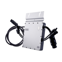
Mount the PV modules above the
microinverter.
B )
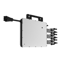
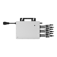
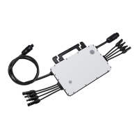
Connect the PV modules’ DC cables to the
DC input side of the microinverter.
Note:
1. Tightening torque of the cap: 5.5±0.5 N·m. Please do not over-torque.
2. Torque of locking screw: 0.4±0.1 N·m.
3. Do not damage the sealing ring in the 3P-AC Trunk Connector during disassembly and assembly.
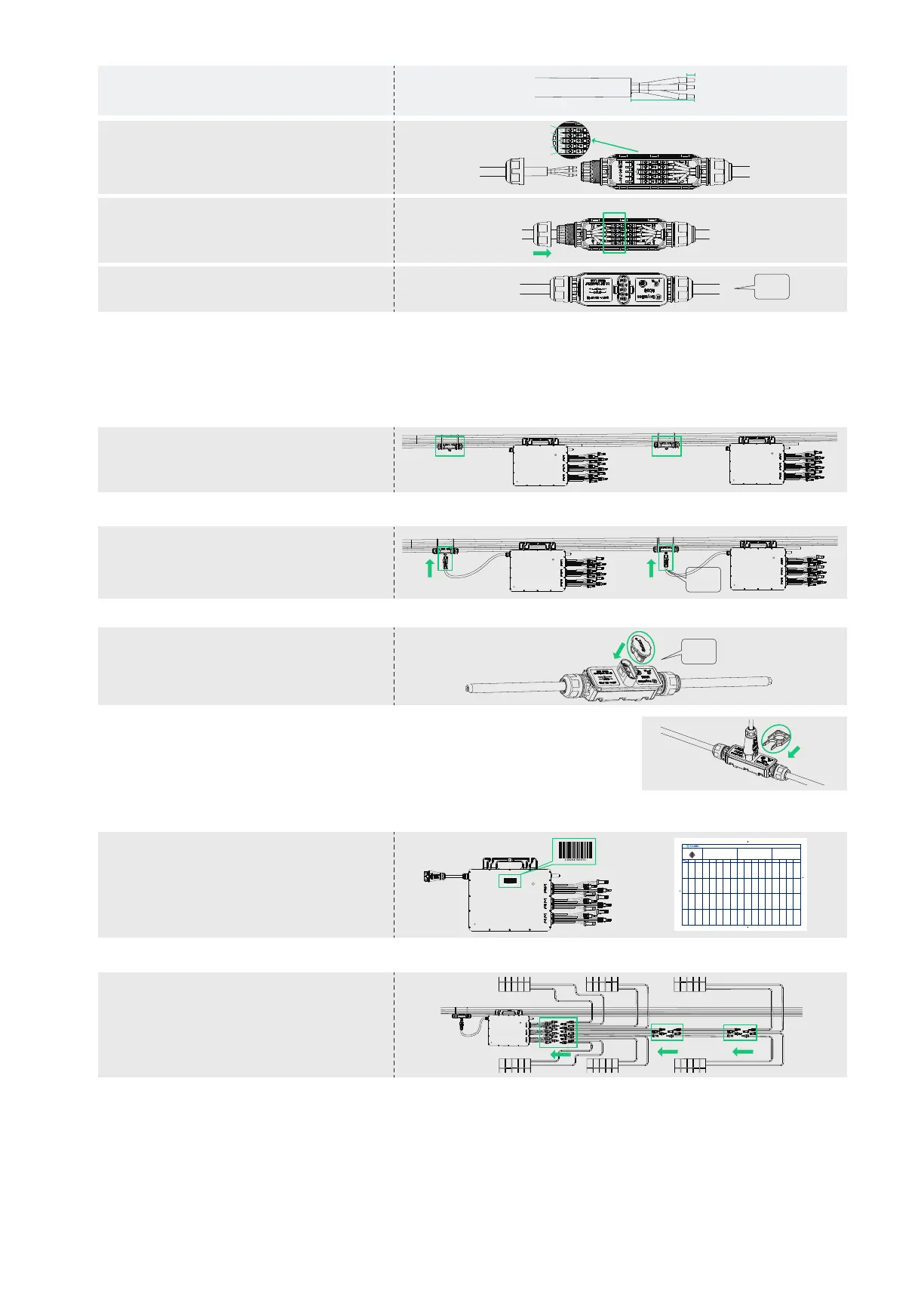
Step 4. Create an Installation Map
A )
Peel the removable serial number label from
each microinverter.
B )
Affix the serial number label to the respective
location on the installation map (please refer
to the appendix).
Note:
1. Make sure that the 3P-AC Trunk Connectors are kept away from any water-channeling surface.
2. In case you need to remove the microinverter AC cable from 3P-AC Trunk Connector, please use
the 3P-AC Trunk Port Disconnect Tool and insert the tool into the side of AC Sub Connector to
complete the removal.
Product information is subject to change without notice. (Please download reference manuals at www.hoymiles.com).
C ) Repeat the above steps to make all the 3P-AC Trunk Cables you need, then lay out the cable on the rail in the suitable
position so that the microinverters can be connected to the Trunk connectors.
Step 3. Complete the AC Connection
Note: Please use DC extension cables.
- Prepare a segment of AC cable with suitable
lengthto connect to the distribution box, with
stripping requirements fulfilled.
- Insert the cable into the cap in a way that
theL1, L2, L3, PE and N lines are in correspond-
ing slots.
- Tighten the screws: and tighten the cap back
to the port.
- Plug the upper cover back to the Trunk
connector.
Region: Global AP040390 REV1.1 © 2020 Hoymiles Power Electronics Inc. All rights reserved. 02
B ) Connect the AC end cable to the distribution box, and wire it to the local grid network.
A) Turn on the AC breaker for the branch circuit.
B) Turn on the main AC breaker for the house. Your
system will start to generate power in about two
minutes.
Step 7. Set up Monitoring System
Please refer to the DTU User Manual or DTU Quick Install Guide,
and Quick Installation Guide for S-miles Cloud to install the DTU
and set up monitoring system.
D ) Attach the 3P-AC Trunk Cable to the
mounting rail and fix the cable with tie wraps.
A ) Push the AC Sub Connector from
microinverter to the 3P-AC Trunk Connector
until it clicks.
C ) Please plug the 3P-AC Trunk Port Cap in
any vacant AC Trunk Port to make it water and
dust-proof.
5.5±0.5N·m
0.4±0.1N·m
click
click
click
8±1mm
70±5mm
N
PE
L3
L2
L1
To sheet ______
To sheet ______
To sheet ______
To sheet ______
Sheet_____of_____
Hoymiles Microinverter Installation Map
Please Make N for North
1
A
B
C
D
2 3 4 5 6 7 8 9 10 11 12 13 14 15 16
COLUMN
ROW
AP040228 V1.3
Customer Information: DTU Serial Number
Azimuth:
Tilt:
Panel type:
 Loading...