Performance Check
Model
1332A
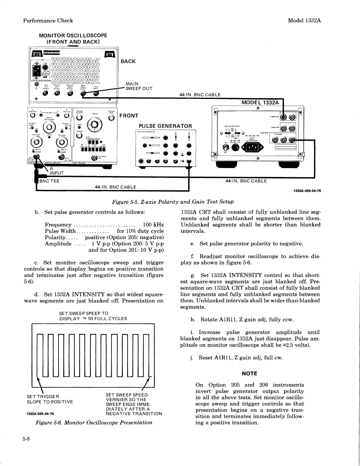
Figure 5-5. Z-axis Polarity and Gain Test Setup
b. Set pulse generator controls as follows:
Frequency
........................
100 kHz
Pulse Width..
...........
for 10% duty cycle
Polarity.
....
positive (Option 205: negative)
Amplitude
.....
1
V
p-p (Option 200: 5
V
p-p
and for Option 201: 10
V
p-p)
c. Set monitor oscilloscope sweep and trigger
controls so that display begins on positive transition
and
teiminates just after negative transition (figure
5-6).
d. Set
1332A INTENSITY so that widest square-
wave segments are just blanked off. Presentation on
SET SWEEP SPEEP TO
DISPLAY
10
FULL CYCLES
I
1
1
SET TRIGGER
SLOPE TO POSITIVE
SET SWEEP SPEED
VERNIER SO THE
SWEEP ENDS IMME-
DIATELY AFTER A
NEGATIVE TRANSITION
1332A CRT shall consist of fully unblanked line seg-
ments and fully unblanked segments between them.
Unblanked segments shall be shorter than blanked
intervals.
e. Set pulse generator polarity to negative.
f. Readjust monitor oscilloscope to achieve dis-
play as shown in figure
5-6.
g. Set 1332A INTENSITY control so that short-
est square-wave segments are just blanked off. Pre-
sentation on
1332A CRT shall consist of fully blanked
line segments and fully unblanked segments between
them. Unblanked intervals shall be wider than blanked
segments.
h.
Rotate AlR11,
Z
gain adj, fully ccw.
i. Increase pulse generator amplitude until
blanked segments on
1332A just disappear. Pulse am-
plitude on monitor oscilloscope shall be 22.5 volts).
j. Reset
AlR11,
Z
gain adj, full cw.
NOTE
On Option 205 and 206 instruments
invert pulse generator output polarity
in all the above tests. Set monitor oscillo-
scope sweep and trigger controls so that
-
-
presentation begins on a negative tran-
sition and terminates immediately
follow-
Figure
5-6.
Monitor Oscilloscope Presentation
ing a positive transition.
Scans by ArtekMedia © 2008