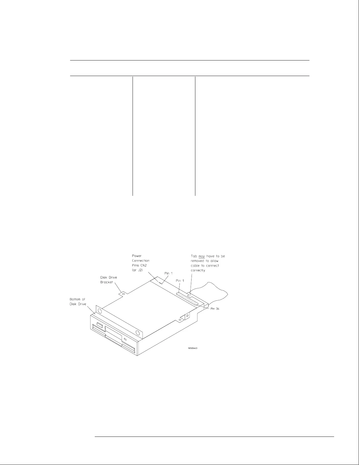
5 Check for the following voltages and signals using an oscilloscope.
Disk Drive Voltages
Pin Signal
Description
Pin Signal
Description
Pin Signal Description
1 NC 13 Ground 24 Write Gate
2NC14NC25Ground
3 NC 15 Ground 26 Track 00
4 NC 16 Motor On 27 Ground
5 NC 17 Ground 28 Write Protect
6 NC 18 Direction 29 Ground
7 Ground 19 Ground 30 Read Data
8 Index 20 Step 31 Ground
9 Ground 21 Ground 32 Side Select
10 Drive Select 22 Write Data 33 Ground
11 Ground 23 Ground 34 Disk Change
12 Drive Select
6 Select Stop, and turn off the logic analyzer. Remove the power cable.
7 Disconnect the disk drive cable and reinstall the disk drive in the mainframe.
8 Reconnect the disk drive cable and install the cover on the mainframe.
Troubleshooting
To test the flexible disk drive voltages
5–25
 Loading...