Do you have a question about the HP 1660 Series and is the answer not in the manual?
Provides contact information for sales and service offices worldwide.
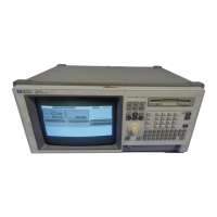
Lists the main features of the HP 1660 Series Logic Analyzers, including the oscilloscope capabilities.
Outlines the service strategy, which is assembly replacement, and suggests returning units to HP for service.
Lists accessories supplied with and available for the HP 1660 Series Logic Analyzers.
Details the performance standards for the logic analyzer functions, including speed and timing.
Lists the specifications for the oscilloscope functions integrated into the HP 1660AS series.
Lists the equipment recommended for testing the logic analyzer functions.
Steps to safely connect and turn on the logic analyzer, including fuse checks.
Procedure for setting the correct line voltage and fuse for instrument operation.
Detailed steps for running built-in diagnostic self-tests for performance verification.
Procedure to test the accuracy of the logic analyzer's threshold settings across different pods.
Test to verify the minimum detectable glitch capability of the logic analyzer.
Verifies the DC voltage measurement accuracy using dual cursor measurements.
A template for recording the results of logic analyzer performance tests.
Provides instructions for calibrating the oscilloscope circuitry of the HP 1660AS series.
Steps for adjusting the CRT monitor's alignment using a grid pattern and yoke.
Explains how to use flowcharts as the primary tool to isolate defective assemblies.
Describes how to check the automatic power-up tests performed by the logic analyzer.
Instructions for running various self-tests to identify operational issues.
Procedure to check the power supply voltages using loaded and unloaded conditions.
Instructions for removing and replacing the internal disk drive.
Steps for removing and replacing the instrument's power supply unit.
Procedure for removing and replacing the central processing unit (CPU) board.
Instructions for removing and replacing the front panel and keyboard assembly.
Guidance on how to return assemblies to Hewlett-Packard for service or replacement.
Information on how to order replacement parts, including listing and non-listed items.
A detailed list of all replaceable parts with their designations and HP part numbers.
Provides a high-level overview of the logic analyzer's block diagram and functions.
Explains the theory of operation for the logic acquisition boards.
Describes the different types of self-tests and their purpose.
| Category | Logic Analyzer |
|---|---|
| Glitch Trigger | Yes |
| Pattern Trigger | Yes |
| State Analysis | Yes |
| Transitional Timing | Yes |
| Trigger Modes | Edge, Pattern, Glitch |