Verify the test signal
11 Check the clock pulse width. Using the oscilloscope, verify that the clock pulse
width is 3.50 ns, +0 ps or − 100 ps.
aa Enable the pulse generator channel 1 and channel 2 outputs (with the LED off).
bb In the oscilloscope Timebase menu, select Delay. Using the oscilloscope knob,
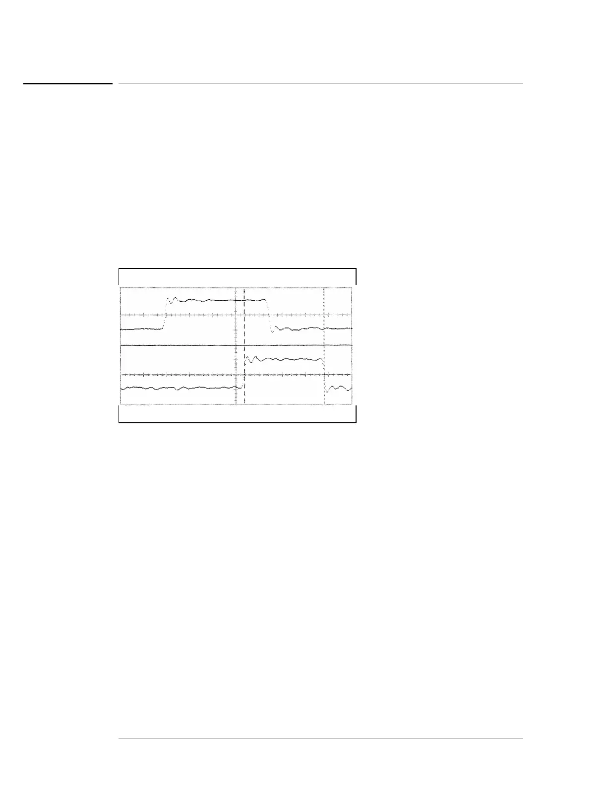
position the clock waveform so that the waveform is centered on the screen.
cc In the oscilloscope Delta V menu, set the Marker 1 Position to Chan 2, then set Marker
1 at − 1.3000 V. Set the Marker 2 Position to Chan 2, then set Marker 2 at − 1.3000 V.
dd In the oscilloscope Delta T menu, select Start On Pos Edge 1. Select Stop On Neg
Edge 1.
ee If the pulse width is outside of the limits, adjust the pulse generator channel 2 width
and select the oscilloscope Precision Edge Find until the pulse width is within limits.
22
Check the clock period. Using the oscilloscope verify that the clock period is 10 ns,
+0 ps or − 250 ps.
aa In the oscilloscope Timebase menu, select Sweep Speed 2.00 ns/div.
bb Select Delay. Using the oscilloscope knob, position the clock waveform so that a
rising edge appears at the left of the display.
cc In the oscilloscope Measure menu, select Measure Chan 2, then select Period. If the
period is more than or equal to 10.000 ns, go to step 4. If the period is less than 10.000
ns but greater than 9.75 ns, go to the next page.
dd In the oscilloscope Timebase menu, add 10 ns to the Delay.
ee In the oscilloscope Measure menu, select Period. If the period is more than or equal
to 10.000 ns, decrease the pul se generator Chan 2 DOUB in 10 ps increments until one
of the two periods measured is less than 10.000 ns but greater than 9.75 ns.
To test the multiple-clock, multiple-edge, state acquisition (logic analyzer)
3–40

 Loading...


