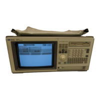
To remove and replace the rear panel assembly
11 Using previous procedures, remove the following assemblies:
•
Handle
•
Rear Feet
•
Cover
22
Remove the switch actuator cable from the line filter according to "To remove and
replace the switch actuator assembly."
33 Disconnect the BNC In/Out and fan cables on the acquisition board.
44 Disconnect the RS-232C an HP-IB cables from the CPU board.
55 For the HP 1660AS-series Logic Analyzers, remove the hex nut and lock washer from
the BNC Cal ports.
66 Remove the two screws connecting the keyboard connector socket to the rear panel.
77 Remove the six rear panel screws.
88 Lift the rear panel away from the chassis.
99 Reverse this procedure to install the rear panel.
Check that the following assemblies are properly installed before installing the rear panel:
•
Monitor
•
Acquisition Board
•
Oscilloscope Board (HP 1660AS-series only)
When installing the rear panel, check that the alignment tabs on the acquisition board are
lined up with the corresponding holes in the rear panel.
Replacing Assemblies
To remove and replace the rear panel assembly
6–9

 Loading...