Set up the logic analyzer
11 Set up the Configuration menu.
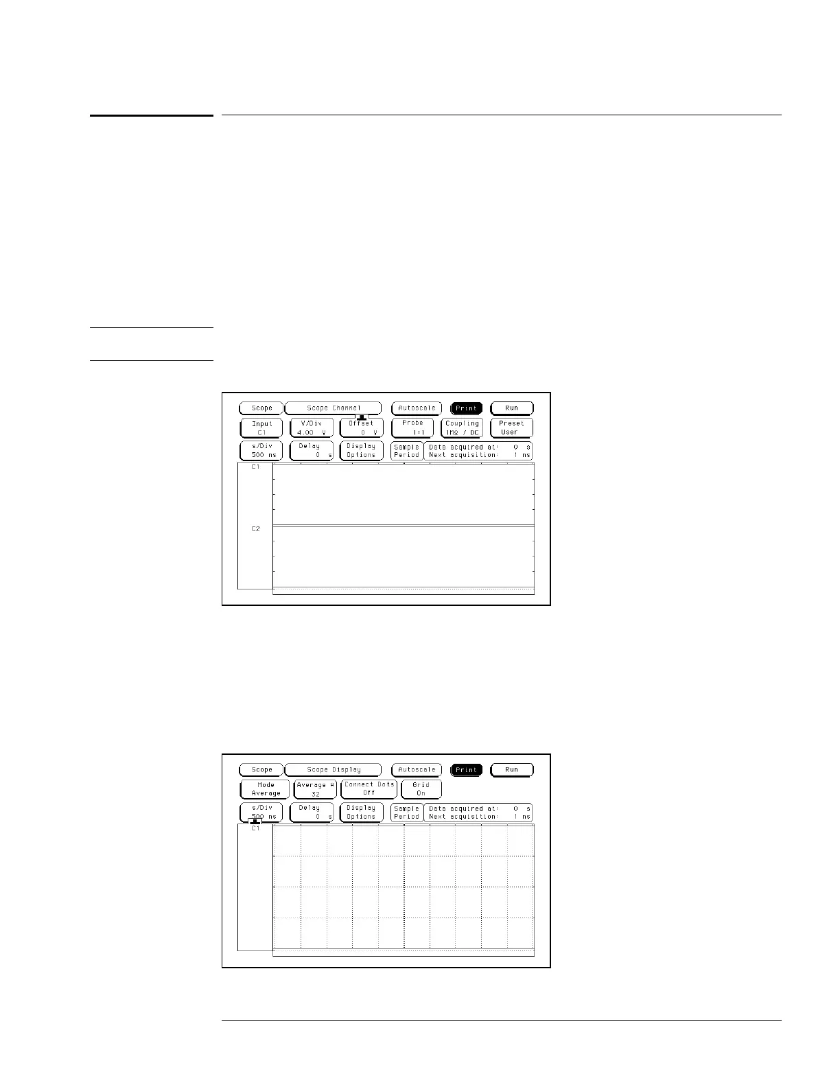
aa Press the Config key. At the pop up menu, select Scope Channel.
bb Select the Input field, then select C1.
cc Move the cursor to the Probe field, then use the RPG knob to dial in 1:1.
dd Move the cursor to the V/Div field, then use the PRG knob to dial in 4.00 V.
ee Move the cursor to the Offset field. Set the offset to 0 by typing 0, then pressing the
Select key.
ff Select the Coupling field, then select 1MΩ / DC.
Caution
Set the Channel Coupling field to 1MΩ / DC or damage to the equipment will result.
gg Move the cursor to the s/Div field, then use the RPG knob to dial in 500 ns.
22
Set up the Display menu.
aa Press the Display key.
bb Select the Mode field, then select Average.
cc Move the cursor to the Average # field. Type 32 on the front-panel keyboard, then
press Done.
dd Select the Grid field and set it to On.
ee In the Waveform menu, delete channel 2. If channel 1 is not inserted, insert channel 1.
To test the offset accuracy (oscilloscope)
3–77

 Loading...


