Set up the logic analyzer
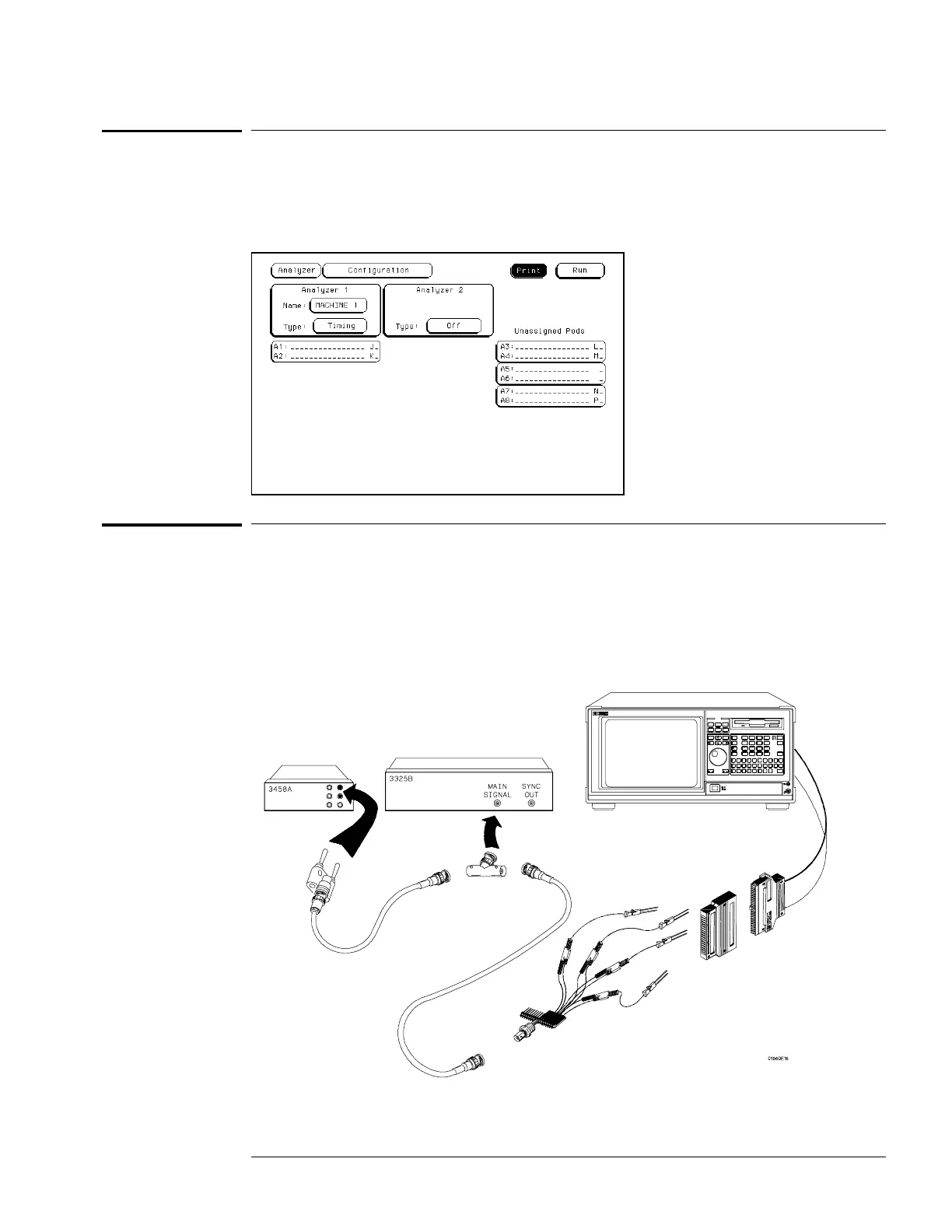
11 Press the Config key.
22 Unassign Pods 3 and 4, Pods 5 and 6, and Pods 7 and 8. To unassign the pods, select
the pod field. In the pop-up menu, select Unassigned.
Connect the logic analyzer
11 Using the 17-by-2 test connector, BNC cable, and probe tip assembly, connect the
data and clock channels of pod 1 to one side of the BNC Tee.
22 Using a BNC-banana cable, connect the voltmeter to the other side of the BNC Tee.
33 Connect the BNC Tee to the Main Signal output of the function generator.
Testing Performance
To test the threshold accuracy (logic analyzer)
3–9

 Loading...


