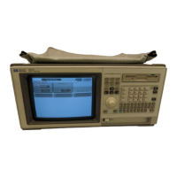
To remove and replace the handle
• Remove the two screws in the endcaps, then lift off the handle.
To remove and replace the feet and tilt stand
11 Remove the screws connecting the four rear feet to the instrument.
22 Separate the rear feet from the instrument to remove them.
33 Press the locking tab on the bottom feet, then remove them.
44 Remove the tilt stand from the bottom front feet by lifting the stand up and out of the
foot.
55 Reverse this procedure to install the feet and tilt stand.
To remove and replace the cover
11 Remove the probe plate and disconnect the logic analyzer cables from the rear panel.
22 Using the previous procedures, remove the handle and the four rear feet.
33 Remove the seven screws from the front molding, then slide the molding forward to
remove it.
44 Remove the cover.
To remove t he cover, set t he inst rument upright and facing t oward you. Slide the chassis
toward the front, out of the cover, and set it on a static-safe work area.
55
Reverse this procedure to install the cover.
Check that all assemblies are properly installed before installing the cover.
When installing the chassis in the cover, check t hat t he tabs locat ed at t he bott om, rear of
the cover align with the holes in the rear panel.
Replacing Assemblies
To remove and replace the handle
6–5

 Loading...