To test the logic analyzer probe cables
This test allows you to functionally verify the probe cable and probe tip assembly of any of
the logic analyzer pods. Only one probe cable can be tested at a time. Repeat this test for
each probe cable to be tested.
Equipment Required
Equipment Critical Specification Recommended
Model/Part
Pulse Generator 100 MHz, 3.5 ns pulse width,
< 600 ps rise time
HP 8131A Option 020
Adapter (Qty 4) SMA (m) - BNC (f) HP 1250-1200
Coupler (Qty 4) BNC (m)(m) HP 1250-0216
6x2 Test Connectors (Qty 4)
11 Turn on the equipment required and the logic analyzer.
22 Set up the pulse generator.
aa Set up the pulse generator according to the following table.
Pulse Generator Setup
Channel 1 Channel 2 Period
Delay: 0 ps Delay: 0 ps 100 ns
Dty: 50% Dty: 50%
High: 3.00 V High: 3.00 V
Low: 0.00 V Low: 0.00 V
bb Enable the pulse generator channel 1 and channel 2 outputs (with the LEDs off).
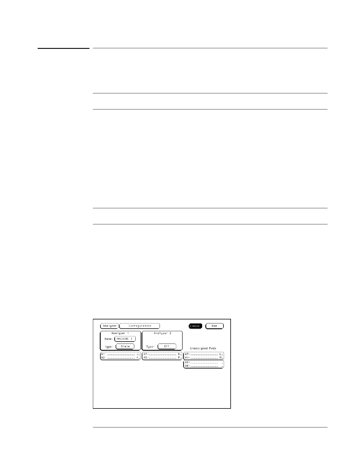
33 Set up the logic analyzer Configuration menu.
aa Press the Config key.
bb In the Analyzer 1 box, select the field to the right of Type, then select State.
Troubleshooting
To test the logic analyzer probe cables
5–29

 Loading...


