Verify the test signal
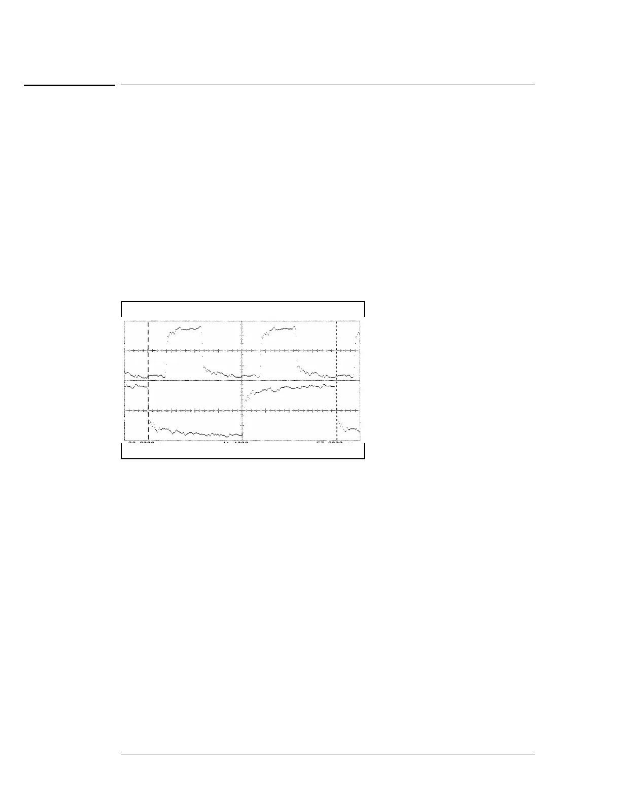
11 Check the clock period. Using the oscilloscope, verify that the clock period is 20 ns,
+0 ps or − 250 ps.
aa Enable the pulse generator channel 1 and channel 2 outputs (with the LED off).
bb In the oscilloscope Timebase menu, select Sweep Speed 2.50 ns/div.
cc Select Delay. Using the oscilloscope knob, position the clock waveform so that a
falling edge appears at the left of the display.
dd In the oscilloscope Measure menu, select Measure Chan 2, then select Period. If the
period is less than 20.000 ns, go to the next page. If the period is more than or equal
to 20.000 ns, go to step 5.
ee In the oscilloscope Timebase menu, add 10 ns to the Delay.
ff In the oscilloscope Measure menu, select Period. If the period is more than or equal
to 20.000 ns, decrease the pulse generator period in 100 ps increments until the
period measured is less than 20.000 ns.
To test the single-clock, multiple-edge, state acquisition (logic analyzer)
3–52

 Loading...


