44 Set up the Marker menu.
aa Press the Marker key.
bb Move the cursor to the V Markers field and press Select. The voltage markers should
now be On.
cc Select Va on C1.
dd Select Vb on C1.
ee If the T markers are On, turn the T markers Off by moving the cursor to the T markers
field and pressing Select. Select Off.
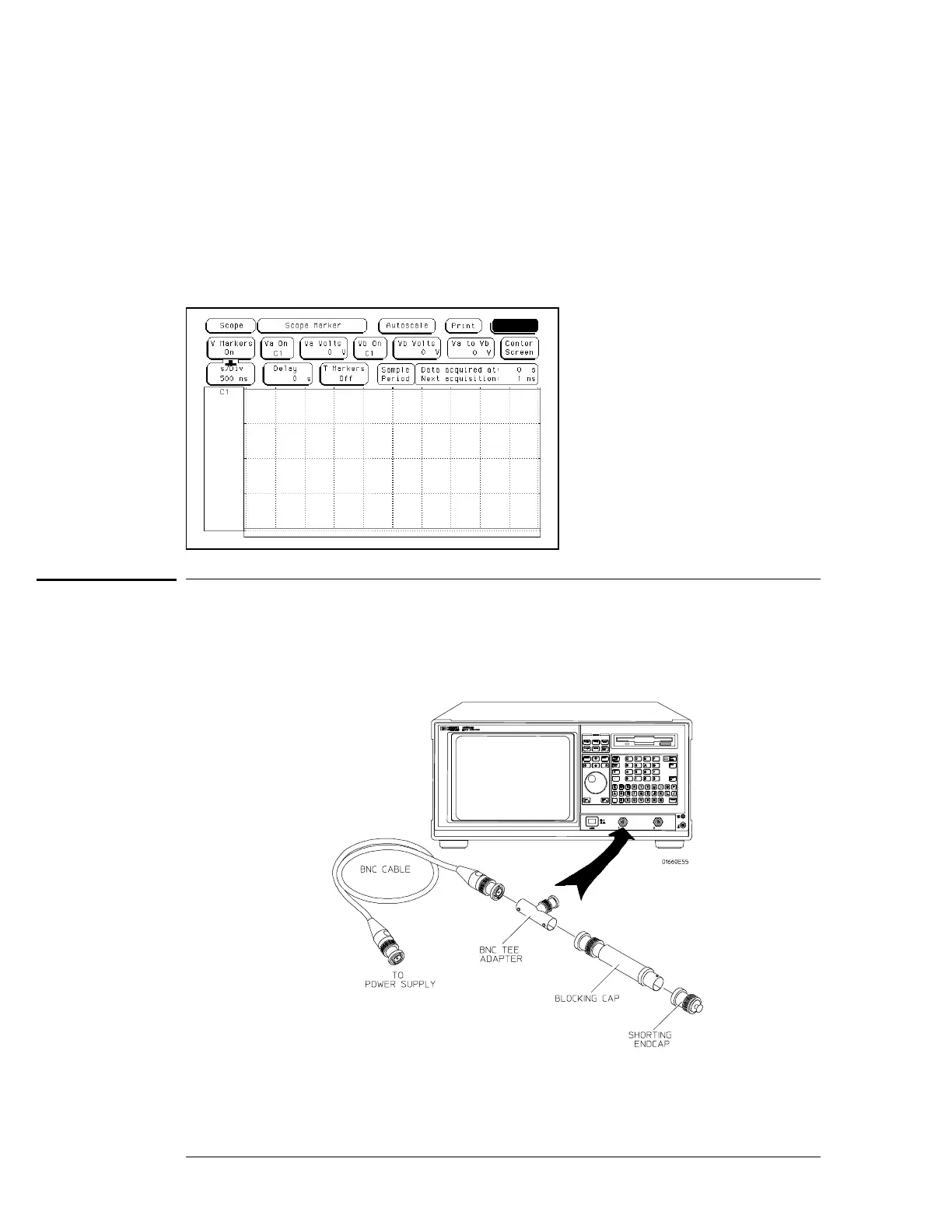
Connect the logic analyzer
11 Using a BNC-to-banana adapter, connect one end of the cable to the power supply. Connect
the BNC tee, the blocking capacitor, and the shorting endcap to the other end of the cable.
22 Monitor the power supply output with the Digital Multimeter.
To test the voltage measurement accuracy (oscilloscope)
3–74

 Loading...


