Check the setup/hold with single clock, multiple clock edges
11 Select the logic analyzer setup/hold time.
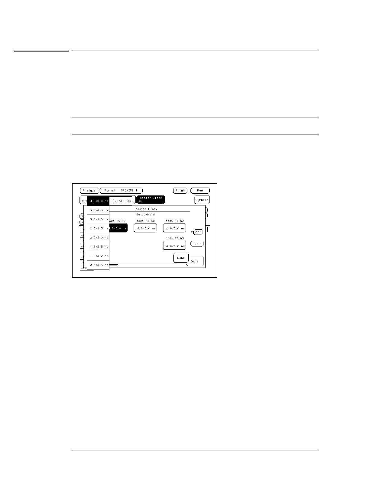
aa In the logic analyzer Format menu, select Master Clock.
bb Select and activate any mul tipl e clock edge.
cc Select the Setup/Hold field, then select the setup/hold to be tested for all pods. The
first time through this test, use the top combination in the following table.
Setup/Hold Combinations
4.0/0.0 ns
0.0/4.0 ns
2.0/2.0 ns
dd Select Done to exit the setup/hold combinations.
22
Disable the pulse generator channel 1 COMP (with the LED off).
33 Using the Delay mode of the pulse generator channel 2, position the pulses according
to the setup time of the setup/hold combination selected, +0.0 ps or − 100 ps.
aa In the oscilloscope Delta V menu, set the Marker 1 Position to Chan 1, then set
Marker 1 at − 1.3000 V. Set the Marker 2 Position to Chan 2, then set Marker 2 at
− 1.3000 V.
bb In the oscilloscope Delta T menu, select Start on Pos Edge 1. Select Stop on Neg
Edge 1.
To test the single-clock, multiple-edge, state acquisition (logic analyzer)
3–54

 Loading...


