To make the test connectors (logic analyzer)
The test connectors connect the logic analyzer to the test equipment.
Materials Required
Description Recommended Part Qty
BNC (f) Connector HP 1250-1032 5
100 Ω 1% resistor HP 0698-7212 8
Berg Strip, 17-by-2 1
Berg Strip, 6-by-2 4
20:1 Probe HP 54006A 2
Jumper wire
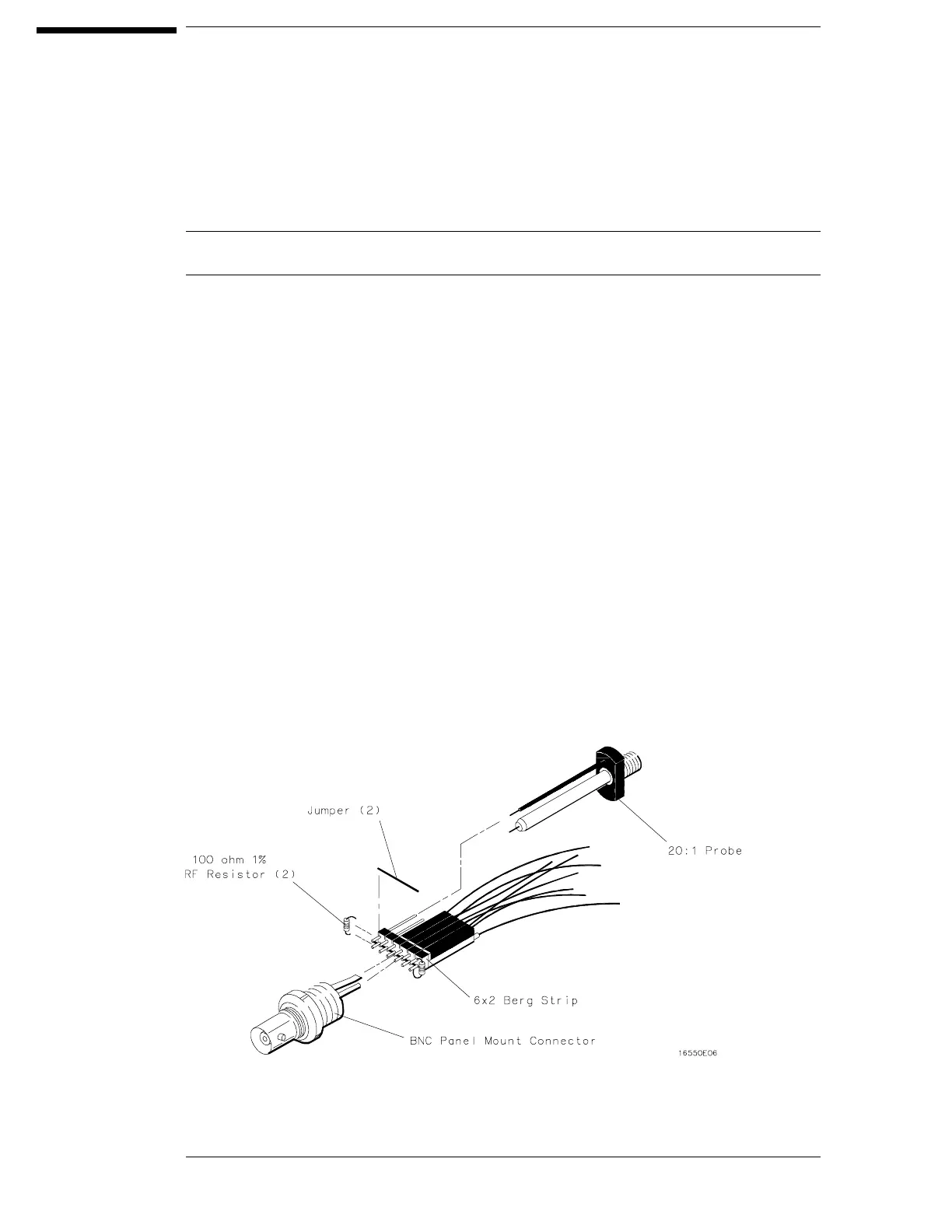
11 Build four test connectors using BNC connectors and 6-by-2 sections of Berg strip.
aa Solder a jumper wire to all pins on one side of the Berg strip.
bb Solder a jumper wire to all pins on the other side of the Berg strip.
cc Solder two resistors to the Berg strip, one at each end between the end pins.
dd Solder the center of the BNC connector to the center pin of one row on the Berg strip.
ee Solder the ground tab of the BNC connector to the center pin of the other row on the
Berg strip.
ff On two of the test connectors, solder a 20:1 probe. The probe ground goes to the
same row of pins on the test connector as the BNC ground tab.
3–6

 Loading...


