Performance Tests
PERFORMANCE TESTS
21
48
=
c:::=l
t:::=:J
c:=::::::J c:::::::::J
011
110
o
()
0
o (
SAM
PLING
OSC
IL
LOSCOPE
D
<y
0 (
W
2~8
50W
Figure
4-11
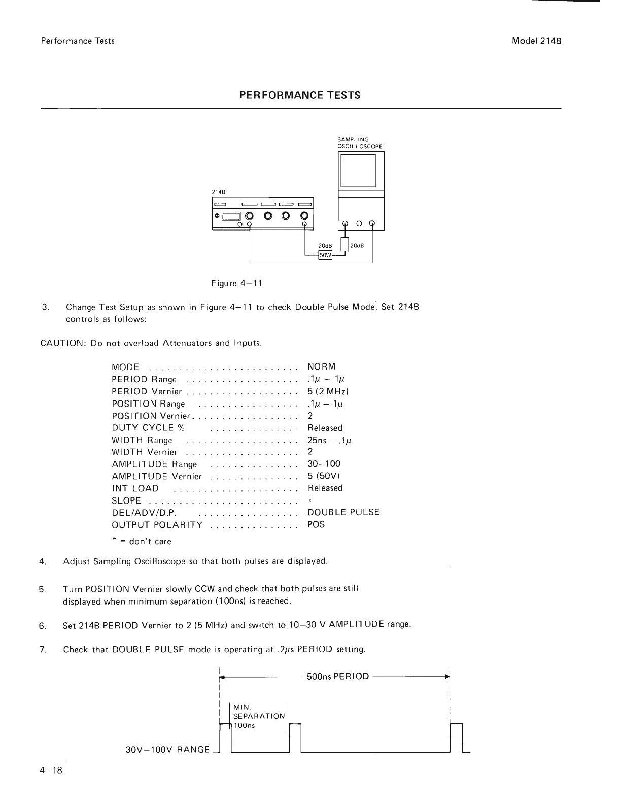
3.
Change Te
st
Setup
as
s
hown
in Figure 4-
11
to
check Double Pulse Mode: Set 214B
controls
as
follows
:
CAUTION
: Do
not
overload
Attenuato
rs
and Inputs.
MODE . .
....
..
. . . . .
.....
...
.
...
NORM
PERIOD
Range . .
..
...
.
...
..
.....
. .
1p
-
lp
PERIOD
Vernier.
. . . . . . . . . . . . . . . .
..
5 (2 MHz)
POSITION Range .
.....
. .
.....
. . . . .1p -
lp
POSITION Vernier . . . . . . . . . . . . . . . .
..
2
DUTY
CYCLE
% . . . . . . . . . . . . . . .
Released
WIDTH
R
ange
.
...
. . .
.. ..
. .
...
..
. 25ns - .1p
WIDTH
Vernier .
..
.
...
.... ....
..
. . 2
AMPLITUDE
Range
.....
...
.
..
.
...
30- 100
AMPLITUDE
Vernier .
...
........
.
..
5
(50V)
INT
LOAD
.............
..
. . . .
..
Released
SLOPE
......
...
.
..
.
....
.
..
...
. .
DEL!ADV
/D.P. . . . . . . . . . . . . . . .
..
DOUBLE
PULSE
OUTPUT
POLARITY
...
.
...........
POS
* =
don't
care
4.
Adjust
Sampling
Osc
illoscope
so
that
both
pulses
are
displayed.
5.
Turn
POSITION Vernier slowly
CCW
and check
that
both
pulses
are
still
displayed when
minimum
separation (lOOns)
is
reached.
6.
Set 214B PERIOD Vernier
to
2 (5 MHz) and switch
to
10
-3
0 V
AMPLITUDE
range.
7.
Check
that
DOUBLE
PULSE mode
is
operating at .2ps PERIOD setting.
I
,..
I
I
500ns PERIOD
----
-
~~
I
I
I
I
I
30V
-
l00V
RANGE
4- 18
MIN
. I
S
EPARATION
l
OOns
I
I
Model 214B
Scans by ArtekMedia => 2009