Model 3314A
Installation
4.
Clean
the air filter.
2·8.
WHAT
TO
DO
IN
CASE
OF
DIFFICULTY
2. Check the Line Voltage
and
the Line Voltage Selec-
tor.
These must be compatible.
3. Check the Line Fuse for
the
proper
value
and
type.
Normal
blow type fuses are
not
allowed.
SW/TR
INTVL
START FREQ
STOP
FREQ
MARK FREQ
I
LED
In addition, you can now check every front panel key.
When a key is pressed, a corresponding
LED
should go
OFF. The Modify knob
and
arrow keys cause elements
of
the 7 segment display to go OFF.
1. Clear the 3314A's memory completely by holding
the
PRESET
key in while setting power ON. The 3314A
Will
display
"E09"
after the normal start up to indicate
the the non-volatile memory has been cleared.
There are several operator actions
that
should be per-
formed before an 3314A is diagnosed as defective.
1111
ROM
IC
ILED
IRAM rc
U208
FREQ
U211
AMPTD
U207 OFFSET
SYM
PHASE
N
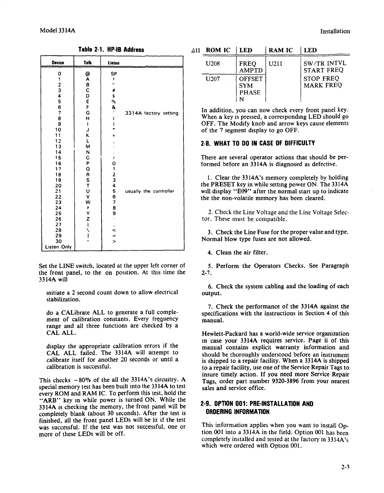
Device
Talk
Listen
0
@
SP
1
A
I
2
B "
3
C
#
4 D $
5 E
%
6 F
&
7 G
3314A
factory setting
8
H
(
9
I
)
10
J
.
11
K
+
12 L
13
I
M
-
14 N
15
0
I
16 P
0
17
Q
1
18
R 2
19
S
3
20
T
4
21
U
5
usually the
controller
22 V 6
23
W 7
24
)l
8
25
y
9
26 Z
27
I
28
\
<
29
I
=
30
A
>
Usten
Only
Table
2·1.
HP·IB
Address
Set the LINE switch, located at the upper left corner of
the
front panel, to the on position. At this time the
3314A will
initiate a 2 second count down to allow electrical
stabilization.
5.
Perform
the Operators Checks. See Paragraph
2-7.
6. Check the system cabling
and
the
loading
of
each
output.
do a
CAlibrate
ALL to generate a full comple-
ment
of
calibration constants. Every frequency
range
and
all three functions are checked by a
CAL ALL.
display the appropriate calibration errors if the
CAL ALL failed. The 3314A will
attempt
to
calibrate itself for another 10 seconds or until a
calibration is successful.
This checks -80070 of the all the 3314A's circuitry. A
special memory test has been built into the 3314A to test
every ROM
and
RAM fC. To perform this test. hold the
"ARB"
key m while power is turned ON. While the
3314A IS checking the memory, the front panel will be
completely blank (about 30 seconds). After the test is
finished. all the front panel LEDs will be lit if the test
was successful.
If
the test was not successful, one or
more of these LEDs will be off.
7. Check the performance
of
the 3314A against the
specifications with the instructions in Section 4 of this
manual.
Hewlett-Packard has a world-wide service organization
m case your 3314A requires service. Page
ii
of
this
manual
contains explicit warranty information
and
should be thoroughly understood before an instrument
is shipped to a repair facility. When a 3314A is shipped
to a repair facility, use one
of
the Service Repair Tags to
insure timely action.
If
you need more Service Repair
Tags, order
part
number 9320-3896 from your nearest
sales
and
service office.
2-9.
OPTION
001:
PRE-INSTALLATION
AND
ORDERING
INFORMATION
This information applies when you want to install Op-
tion 001 into a 3314A in the field. Option 001 has been
completely installed
and
tested at the factory in 3314A's
which were ordered with Option 001.
2-3
 Loading...


