Model 3314A
C" Disconnect all five cables from the A3
PC
Assembly.
D. Remove all eight screws that secure the A3
PC
Assembly to the deck.
E. Carefully lift the A3 PC Assembly straight up.
There are three transistors mounted on the deck
that
connect to the A3 PC Assembly
VIa
three connectors on
the left side of the PC board
F Unsolder the collector of A3Q115 and the end
of
A3RI46 that is nearest Q112.
G" Solder a Tie Point (0360-0124) into the empty holes
created in step F.
H. Wrap the lead from A3Q115 around Its tie point.
This lead should make one full
turn
around the tie point
to insure good mechanical contact and the lead should
have a slight bend to relieve any stress.
I Wrap the lead from A3RI46 around its tie point.
This lead should make one full turn around the tie point
to insure good mechanical contact and the lead should
have a slight bend to relieve any stress.
J. Install about .6 inch of flexible tubing on each lead
of
A3CR123.
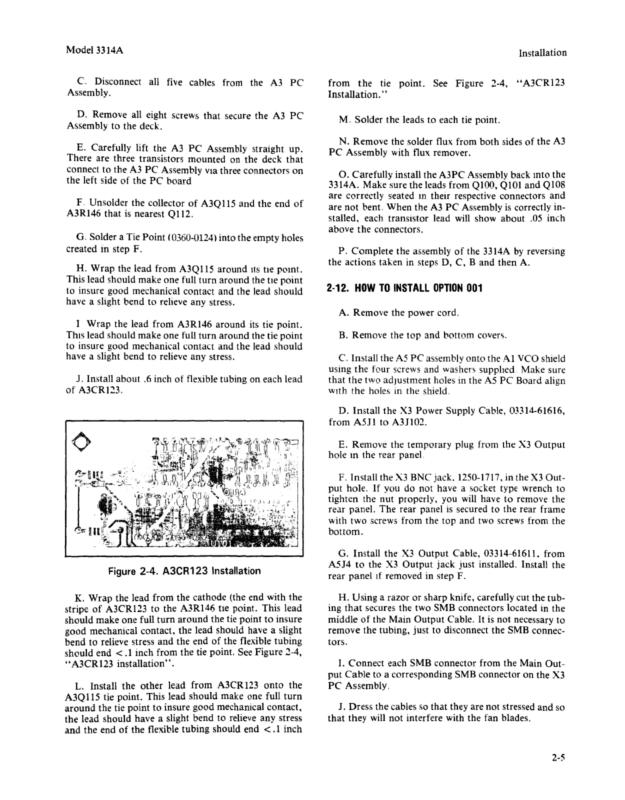
Figure 2-4.
A3CR123
Installation
K. Wrap the lead from the cathode (the end with the
stripe of A3CRl23 to the A3RI46 tte point. This lead
should make one full
turn
around the tie point to insure
good mechanical contact, the lead should have a slight
bend to relieve stress and the end of the flexible tubing
should end
<.1
inch from the tie point. See Figure 2-4,
"A3CR123 installation".
L. Install the other lead from A3CRI23 onto the
A3Q
liS
tie point. This lead should make one full
turn
around the tie point to insure good mechanical contact,
the lead should have a slight bend to relieve any stress
and the end of the flexible tubing should end
<.1
inch
Installation
from
the
tie point. See Figure 2-4, "A3CR123
Installation."
M" Solder the leads to each tie point.
N. Remove the solder flux from both sides of the A3
PC Assembly with flux remover.
O. Carefully install the A3PC Assembly back mto the
3314A. Make sure the leads from
QlOO,
Q101 and Q108
are correctly seated
In
their respective connectors and
are
not
bent, When the A3 PC Assembly is correctly in-
stalled, each transistor lead will show about .05 inch
above the connectors.
P. Complete the assembly
of
the 3314A by reversing
the actions taken in steps D, C, B and then A.
2-12.
HOW
TO
INSTALL
OPTION
001
A. Remove the power cord.
B. Remove the
top
and bottom covers"
C.
Install the A5 PC assembly onto the
Al
VCO shield
using the four screws and washers supplied. Make sure
that
the
two adjustment holes
III
the A5 PC Board align
With the holes
III
the shield,
D. Install the X3 Power Supply Cable, 03314-61616,
from A511 to A3J102.
E. Remove the temporary plug from the X3 Output
hole
10
the rear panel
F. Install the X3
BNe
jack. 1250-1717,in the X3 Out-
put hole.
If
you do not have a socket type wrench to
tighten the nut properly, you will have to remove the
rear panel. The rear panel is secured to the rear frame
with two screws from the top and two screws from the
bottom.
G. Install the X3 Output Cable, 03314-61611. from
A5J4 to the X3 Output jack just installed. Install the
rear panel If removed in step F.
H. Using a razor or sharp knife, carefully cut the tub-
ing
that
secures the two 5MB connectors located in the
middle of the Main Output Cable.
It
is not necessary to
remove the tubing, just to disconnect the 5MB connec-
tors.
I.
Connect each 5MB connector from the Main Out-
put
Cable to a corresponding 5MB connector on the X3
PC Assembly.
J. Dress the cables so that they are not stressed and so
that they will not interfere with the fan blades.
2-5
 Loading...


