Model 34SSA THEORY
OF
OPERATION
Section VIII
8-32.
A separate gain error
measurement is
not
made
for
the 1000 V dc range. Since the only difference between
the 100 V dc and 1000
V
dc
circuit
configuration is a
precise attenuation difference of
10,
the 1000 V dc gain
error constant is computed by the main controller.
$•33.
100 V dc Reference Offset Error Measurement.
Since the reference voltage for the 100 V dc range is
divided by the operational attenuator; a separate offset
error
measurement is made
to
include any offsets which
might be associated with the attenuator and FbT switches
used.
Figure 8-14 illustrates the
circuit
configuration
for
this
measurement.
8-34.
AUTO-CALIBRATION -OHMS.
8-35.
General.
8-36.
During the ohms function the ohms
converter
sup-
plies
a
current through
both the
unknown
resistance and
the reference resistance (see Figure 8-15). Since
the
same
current flows through
both
resistors,
their
respective volt-
age drops are proportional.
As
with the CC Auto-Cal
sequence, the
offset errors are
measured
and
subtracted
from the unknown and reference resistance measurements.
The
voltage developed
across the unknown resistor is mea-
sured
by
closing SI while
the reference
voltage, developed
across the reference resistor, is measured
by
closing S2. The
value
of the
unknown
resistance is computed
by
the main
controller. An equation describing this computation is:
-HVRx
+
6o>Gi
-EoGil
R„
Kr
IVrEF
*
Eol
G2
-
Eo Ga
Figure 8-15.
Basic Ohms Measurement Diagram.
where
Rx
is the unknown resistance value,
V(^x
is the volt-
age
drop across the unknown resistance, V|^
ref. is the volt-
age drop across
the reference resistance,
is (he input
offset error. G| and G
2
are the circuit gains of the
particu-
lar measurements, and
fCr factor. This equation
simplifies to:
,
VRx Cl
VreF
G2
Kr
8-37.
Circuit Description.
8-38.
.1 kn, 1 kf2, 1
Mf2 Offset Error Measurements. The
offset error
constants derived for
the .1 V dc and I V dc
ranges are
also used for the .1
kf7, 1
kfl,
and 1 Mf2 offset
error
constants, since the
circuit configurations are the
same. Refer
to
Paragraph 8-25
for
a
description
of these
offset error measurements.
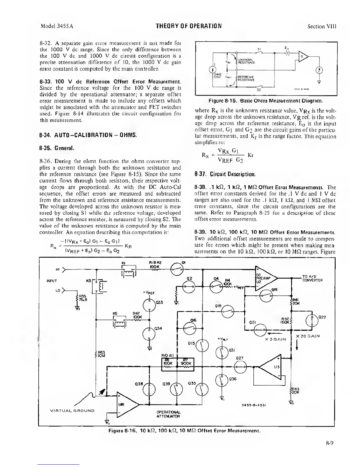
8-39. 10
kn, 100 kn, 10 Mn Offset
Error Measurements.
Two additional
offset measurements
are made to compen-
sate for
errors
which
might be present when
making mea-
surements on
the 10 kn, 100 kn, or 10
Mn
ranges.
Figure
8-9
 Loading...


