Section
VIII
THEORY OF OPERATION
Model 3455A
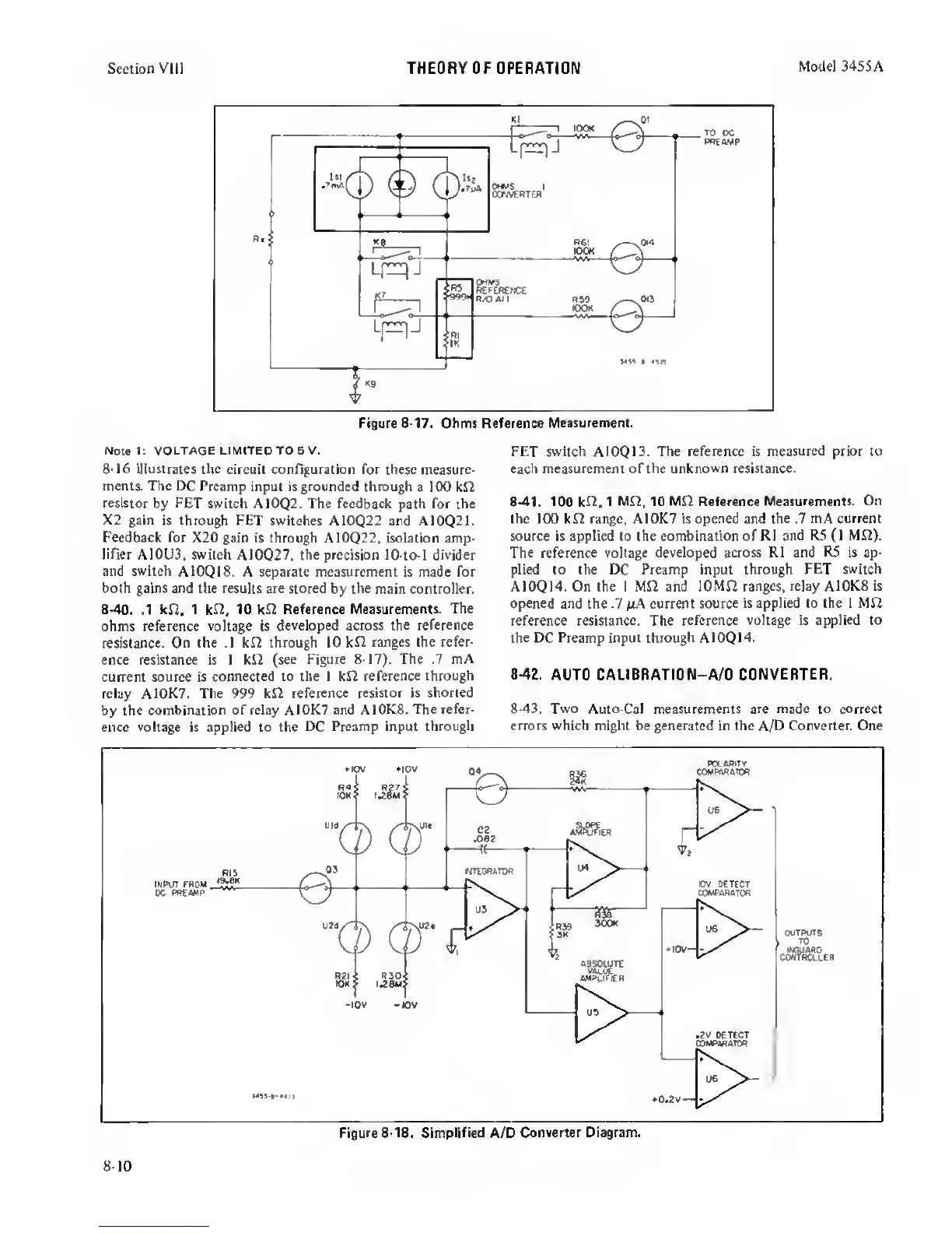
Figure
8-17.
Ohmt Reference
Meaiurement.
Notei: VOLTAGE LIMITED TO
5
V.
FET Switch
A10Q13.
The reference is measured prior to
8-16 illustrates
the circuit configuration for these measure-
each measurement of the
unknown
resistance,
ments. The
DC Preamp input is grounded through
a 100 kf2
resistor
by FET switch A10Q2. The feedback path for the
8-41, 100 1 10 Mf2 Reference
Measurements. On
X2 gain
is
through
FET switches A10Q22 and A10Q21.
the 100 kJ2 range, AI0K7 is opened and the .7 mA
current
Feedback for
X20 gain is through A10Q22, isolation amp-
source is applied to the combination of R1 and
R5
(1
M£2).
lifier AI0U3, switch
A10Q27,
the precision
10-to-l
divider
The
reference voltage developed across R1 and R5 is ap-
and switch
A10Q18. A separate measurement is made for
plied to the DC Preamp input through
FET switch
both gains and the results are stored
by
the
main controller.
A10Q14. On the 1 MJ2 and lOMD
ranges, relay A10K8 is
8-40.
.1 kSl, 1
kn. 10 kf2 Reference
Measurements. The
‘^e .7
M
current
source is applied to the 1 Mfi
ohms reference
voltage
is
developed across the reference
reference resistance. The
reference voltage is applied to
resistance.
On the .1 kfi through 10 kfl
ranges the refer-
^ Preamp input
through
A10Q14.
ence resistance is I kJ2 (see
Figure 8-17). The .7 mA
current source is
connected to the I kJ2 reference
through
8-42.
AUTO
CALIBRATION—
A/0
CONVERTER,
relay A10K7. The 999 kfi reference
resistor is shorted
by the
combination
of
relay AI0K7 and AI0K8. The
refer-
8-43. Two Auto-Cal
measurements
are
made to correct
ence voltage is applied to the DC
Preamp input through
errors which might be generated
in
the A/D Converter. One
Figure 8-18. Simplified
A/D
Converter Diagram.
8-10
 Loading...


