Model
3455A
THEORY OF OPERATION
Section
VIII
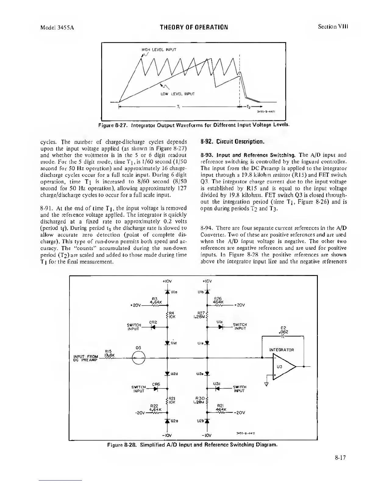
Figure
8-27.
Integrator Output
Waveforms for Oifferettt
Input Voltage
Levels.
cycles. The number of charge-discharge cycles depends
upon the input
voltage
applied (as
shown
in
Figure 8-27)
and whether the voltmeter
is
in the
S
or 6 digit readout
mode. For the 5 digit mode, time
Ti,
is 1/60
second (1/SO
second
for SO
Hz operation) and approximately 16 charge-
discharge cycles occur for a full scale input.
During 6 digit
operation,
time
Ti
is increased to 8/60 second
(8/50
second
for
SO Hz operation), allowing approximately 127
charge/discharge cycles to occur for a full scale input.
8-91.
At the
end
of time Tj,
the input voltage is
removed
and the reference voltage applied. The integrator is quickly
discharged at a fixed rate
to approximately 0.2 volts
(period
tf).
During period the discharge rate is
slowed
to
allow accurate zero detection (point of complete
dis-
charge). This type of run-down permits both speed and ac-
curacy. The “counts” accumulated during the run-down
period
(T
2
)
are scaled and added to those made during time
T
1
for the final measurement.
8-92.
Circuit Description.
8-93. Input
and Reference Switching.
The A/D
input and
reference switching
is
controlled
by
the inguard controller.
The input from the DC Preamp is applied to the integrator
input
through a 19.8 kilohm resistor (RiS) and
FET
switch
Q3.
The integrator
charge
current due
to
the
input
voltage
is
established
by RIS and is
equal to the input voltage
divided
by
19.8 kilohms.
FET
switch
Q3
is closed through-
out the integration period
(time T],
Figure
8-26)
and is
open during periods T
2
and T
3
.
8-94.
There are four separate current references in the A/D
Converter. Two of these are positive references and are used
when the A/D input voltage
is
negative. The other two
references are negative references
and
are used for positive
inputs. In Figure
8-28
the positive references are shown
above
the integrator input line and the negative references
8-17
 Loading...


