Section
VIII
THEORY OF
OPERATION
Model 34SSA
are
below. Both (he
positive
and
negative references
have a
••fast” discharge
reference and a ••slow”
discharge reference.
The fast
discharge references
are used during the Id
cycles
of the integration period to
discharge the
integrator and are
also used for the “fast
run-down” period
(time
tf).
The
“slow” discharge
references arc used during
the •'slow run-
down”
period
(time
1$)
only. Diodes
are
used
to switch the
references
because of their
high speed switching ability.
The following
description uses the positive
“fast-discharge”
reference,
consisting of Uta, R4. CR2
and Uld, to explain
the reference switching
operation. Except
for different
input
levels
to
(he negative reference
switches, operation of
all reference
switching
is
identical.
8-95. During (he lime the
switch
is
turned ••off', diode
CR2 is
forward biased by
approximately
•
2
V
dc on
(he
cathode. Current
flows
from
the + 20 volt supply
through
R4 and CR2.
Under this
condition
the
voltage at the anode
of Uld is
negative (approximately
•
1.5
Vdc)which reverse
biases Uld,
holding it off. (The cathode
of Uld is held at
virtual ground by the
integrator.) During the ••on” condi-
tion. CR2 is
reverse biased
by
applying
approximately
+
3 V dc to the cathode. Diode
Uld becomes forward-
biased and allows the
current to flow through R4 to
the
integrator input. The
purpose of diode Ula is
to compen-
sate for
the voltage drop
across switching diode Uld by
raising the reference
voltage
by
one diode drop. The
refer-
ence
current is determirud by the
voltage across R4 (10
V
dc/IO kilohms^ 1 mA).
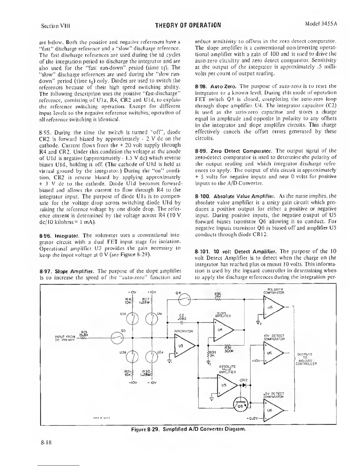
8-96. Integrator.
The voltmeter uses a
conventional inte-
grator circuit
with
a
dual
FET input stage for
isolation.
Operational
amplirwr U3
provides the
gain necessary to
keep
the input
voltage at
0
V (see
Figure 8-29).
8-97.
Slope
Amplifier. The purpose of (he
^ope amplifier
is
to increase (he
speed of the ••auto-xero” function and
reduce sensitivity to offsets in
the aero detect comparator.
The slope
amplifier is
a
conventional
non-inverting operat-
(ional amplifier with a gain
of 100 and is used to
drive the
auto-zero
circuitry and zero detect
comparator. Sensitivity
at
(he output of the integrator is
approximately .5 milli-
volts
per count of output reading.
8-98. Auto-Zero. The purpose of auto-zero is
to reset the
integrator to
a
known level. During this
mode
of
operation
FF.T
switch is
closed, completing the auto-zero loop
through slope
amplifier U4. The integrator
capacitor
(C2)
is used as
the auto-zero capacitor and
stores
a
charge
equal in amplitude and
opposite
in
polarity to any offsets
in
the integrator and
slope amplifier circuits. This charge
effectively cancels (he offset
errors generated by these
circuits.
8-99. Zero Detect Comparator. The output
signal of the
zero-detect
comparator
is
used
to
detennine the polarity of
(he output
reading and which integrator discharge refer-
ences to apply.
The output of this circuit is
approximately
+
5
volts for
negative
inputs and near 0
volts for positive
inputs to the A/D Converter.
8-100. Absolute Value Amplifier. As the
name
implies,
(he
absolute value amplifier is a unity gain
circuit which pro-
duces a
positive output for cither
a
positive or
negative
input. During
positive
inputs,
the negative output of U5
forward
biases transistor
Q6
allowing it to conduct. For
negative inputs transistor
Q6
is biased off
and amplifier
US
conducts through diode CR12.
8-101.
10 volt Detect
Amplifier. The purpose of the 10
volt Detect Amplifier
is
to detect when the charge on the
integrator has reached plus or minus 10
volts. This informa-
tion is
used
by
the inguard controller in determining when
to
apply the discharge references during the
integration per-
8-18
 Loading...


