Model 3455A
THEORY OF
OPERATION
Section
VIII
iod (time
Ti,
Figure 8-26). For inputs
less than 10 volts
the output of the 10
volt Detect j^plifier is near 0
volts.
As (he Input
teaches 10 volts the output switches to
approximately +
5
volts.
8-102.
0.2
volt Detect Amplifier.
The purpose of the .2
volt
Detect Amplifier is to detect
when the integrator has
discharged to
approximately
.2
volts during period T
2
(Figure 8-26). This
information is used
by
the inguard
controller in
determining the point to
remove
the "fast-
discharge” reference and apply the
"slow-discharge”
reference.
8-103.
INGUARD
CONTROLLER.
8-104. General.
8-105. F^ure
8-30 shows
the
basic steps performed by
the
inguard controller. The
inguard controller
receives data con-
taining
range, function, and resolution
information from
the main controller. This data,
containing 36 bits of
infor-
mation and
a
parity bit, is
transferred serially at a
rate
determined
by
the main
controller. The inguard
controller
decodes the information, sets
the input and auto-cal
switches to their required states,
and selects the
appropriate
range, function, and
sample time for the
resolution indi-
cated.
During the measurement
process, the inguard con-
troller manages the
analog-to-digital conversion
sequence
and stores
the digital equivalent of the A/D
input voltage.
8-106.
Upon
completion of the
measurement, the digital
information is transferred from the
inguard controller to
Figure
8-30.
Simplified
Inguard
Controller
Flowchart.
the main controller. This information contains the
measure-
ment
value
and polarity plus a parity bit
and is transferred
serially at a rate
determined
by
(he main controller. The
inguard controller is reset to receive mure
information
by a
reset pulse from the main controller.
8-107.
Circuit Description.
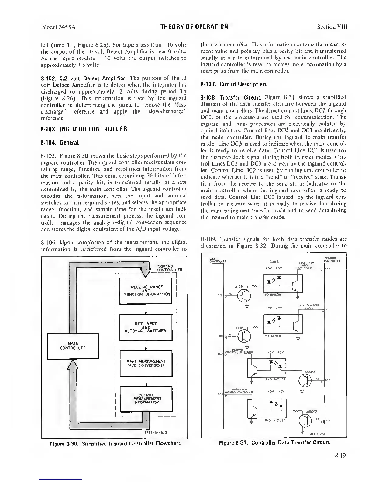
8-108.
Transfer Circuit. Figure
8-31 shows
a
simplified
diagram of the data transfer circuitry between the inguard
and main controllers. The direct
control lines, DCQ) through
DC3, of the processors arc used for communication. The
inguard and main processors are electrically isolated by
optical isolators. Control lines C>C0 and
DCI
are
driven
by
the main controller. During the inguard
to main transfer
mode,
Line
DC0
is used to
indicate when the main control-
ler is ready to receive data. Control Line DC! is used for
the transfer-clock signal during both transfer
modes. Con-
trol
Lines
DC2
and
DC3 arc driven
by
the inguard control-
ler. Control Line DC2 is used
by
the inguard controller to
indicate whether it is in a “send” or "receive” slate. Transi-
tion from the receive to the send status
indicates
to
the
main controller when the inguard controller is
ready to
send data. Control Line DC3 is used by
the inguard con-
troller
to
indicate
when it is ready
to receive data during
the
main-to-inguard transfer
mode
and to
send data during
the inguard to main transfer
mode.
8-109.
Transfer signals for
both data transfer modes are
illustrated in Figure
8-32. During the main controller
to
8-19
 Loading...


