Section
VIII
THEORY OF OPERATION
Model 3455A
Figure
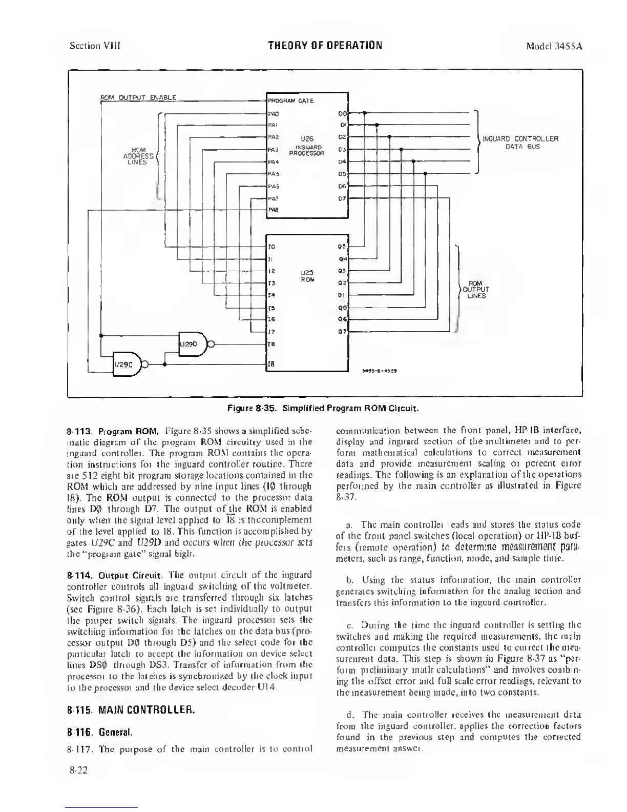
8-35.
Simplified Program ROM Circuit.
8-113. Program ROM. Figure
8-35 shows
a
simplified sche-
malic diagram
of the program ROM circuitry used in the
inguard controller. The program
RO.M contains the opera-
tion
instructions for the inguard controller routine.
There
are 512 eight bit program storage locations
contained in the
ROM which are addressed by
nine input lines
(10
through
18). The ROM
output
is
connected to the
processor
data
lines
D0 through D7. The output ofjlie ROM is enabled
only when the signal level applied to
18
is
thccomplement
of
the
level applied to 18. This function is
accomplished
by
gates Lf29C and 1/29D and occurs wlieri (he processor sets
the
"program gate” signal high.
8-114. Output Circuit. The
output circuit of the inguard
controller controls all
inguard switching of the
voltmeter.
Switch control signals are
transferred through six
latches
(sec Figure 8-36).
Hach latch is set individually to output
the proper switch
signals. The inguard
processor sets the
switching
information for the latches on the data
bus (pro-
cessor output D0 through DS) and the select
code for the
particular latch to accept
the information on
device
select
lines
DS0 through DS3. Transfer of
information from the
processor
to
the latches is synchronized by
(he clock input
to the
processor and (he device select
decoder U14.
8-115.
MAIN CONTROLLER.
8116.
General.
8-1
17.
The purpose of the main controller is
to control
communication
between the front panel. HP-IB interface,
display and inguard
section
of
the multimeter and to per-
form
mathematical calculations to correct
measurement
data and provide
measurement scaling or percent error
readings. The
following is an explanation of the
operations
performed
by
the main controller as
illustrated in Figure
8-37.
a.
The main controller reads and stores the status code
of (he front panel switches flocal operation)
or HP-IB buf-
fers (remote operation) to
determiflO inOaSUremeiU para-
meters, such as range, function,
mode,
and
sample time.
b. Using
the status information, the main
controller
generates
switching
information for the analog section and
transfers this information
to the inguard controller.
c.
During (he time the inguard controller is setting the
switches and making the required measurements, the main
controller computes (he
constants
used
to correct the mea-
surement data.
This step
is
shown in Figure
8-37
as "per-
form preliminary math calculations" and
involves
combin-
ing (he
offset error and full scale error readings, relevant
to
the measurement being made, into two constants.
d. The main
controller receives the measurement data
from the inguard controller, applies the correction factors
found in the
previous
step and
computes the corrected
measurement answer.
8-22
 Loading...


