Model 3455A
THEORY OF OPERATION Section
VIII
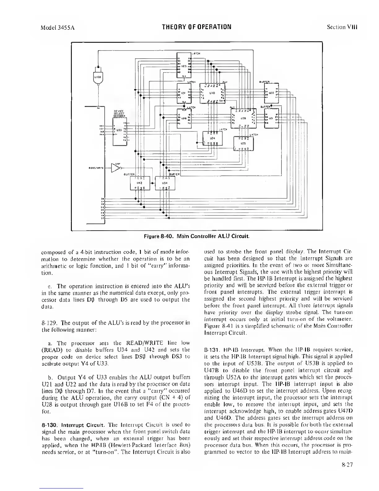
composed of a 4-bi(
instruction code, 1 bit of
mode infor-
mation to determine
whether the operation is to
be an
arithmetic or
logic function, and 1 bit of
“carry” informa-
tion.
e. The operation instruction is
entered into the ALU’s
in the same manner
as the numerical data except, only pro-
cessor data
lines D9 through D5 are used to output the
data.
8-129. The output of the ALU’s is read by
the processor in
the following manner;
a.
The processor
sets the
READ/WRITE line tow
(READ) to
disable buffers U34 and U42 and
sets the
proper code
on device select lines DS0
through DS3 to
activate
output Y4 of
U33.
b. Output Y4
of U33 enables the ALU output
buffers
U2 1 and U22 and
the data Is read by the
processor on data
lines D0 through D7. In the
event
that a
“carry” occurred
during the ALU operation,
the carry output (CN
+
4)
of
U28 is output through
gate U16B to set F4 of the
proecs-
for.
8-130. Interrupt Circuit. The
Interrupt Circuit is used to
signal the main processor when the
front panel switch data
has been changed,
when
an
external trigger has been
applied, when the HP-IB (Hewlett-Packard Interface
Bus)
needs service, or at “turn-on”.
The Interrupt Circuit is also
used to strobe the front
panel display. The Interrupt Cir-
cuit has
been designed so that the Interrupt Signals
arc
assigned priorities. In the
event
of
two or more Simultane-
ous Interrupt Signals,
the one with the highest priority
will
be handled first. The HP-IB Interrupt is assigned
the highest
priority and
will be serviced before the external trigger or
front panel interrupts. The external trigger
interrupt is
assigned the second highest priority and
will be serviced
before the front panel interrupt. All
three interrupt signals
have priority over the display strobe
signal. The turn-on
interrupt occurs only at initial
turn-on of the voltmeter.
Figure
8-41
is a simplified
schematic of the Main Controller
Interrupt Circuit.
8-131. HP-18 Interrupt. When the HP-IB requires
service,
it sets the HP-IB Interrupt signal
high. This signal is applied
to the input of US3B. The
output of U53B is applied to
U47B to disable the front panel
interrupt circuit and
through US2A to the interrupt
gates which set the proces-
sors interrupt input.
The HP-IB interrupt input is also
applied to
U46D to set the interrupt address. Upon recog-
nizing the interrupt input, the
processor sets the interrupt
enable low, to
remove
the
interrupt input, and sets the
interrupt
acknowledge high, to enable address gates U47D
and
U46D. The address gales set the interrupt address on
the processors data bus. It is possible for both the external
trigger interrupt and the HP-IB interrupt to occur simultan-
eously and set their respective interrupt
address
code
on the
processor data bus.
When this
occurs,
the processor is pro-
grammed to vector to the HP-IB Interrupt address
to
main-
8-27
 Loading...


