Section VUl
THEORY OF
OPERATION
Model
3455A
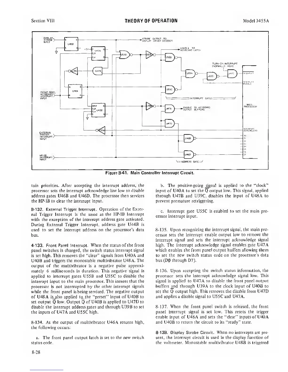
tain priorities. After accepting the interrupt
address, the
processor sets the interrupt acknowledge line
low
to
disable
address gates U46B and U46D. The
processor then services
the HP-IB to dear the
intenupt input.
8-132.
External
Trigger Interrupt. Operation of the
Exter-
nal Trigger Interrupt is the same as
the HP-IB Interrupt
with the exception of the interrupt
address gate activated.
During External Trigger Interrupt,
address gate U44B is
used to set the interrupt address on
the processor’s data
bus.
4-133.
Front
Panel Interrupt. When the status of
the
front
panel switches is changed, the switch status
interrupt signal
is set high. This
removes
the “dear"
signals from U40A and
U40B
and triggers the monostable multivibrator U48A.
The
output of the multivibrator is a
negative pulse approxi-
mately 6 milliseconds
in
duration. This negative signal
is
applied
to
interrupt gates US5B and USSC to disable
the
interrupt input to
the
main
processor. This insures that the
processor
is
not Interrupted
by
the other
interrupt signals
while the front panel is being serviced. The
negative output
of U48A is_also applied
t^the “preset” input of U40B to
set output
Q
low. Output
Q
of U40B is applied to U47D to
disable the interrupt address gates and through
U39B to set
the inputs of U47A and USSC high.
8-134. As the output of multivibrator U46A returns
high,
the following occurs;
a.
The front panel output latch is set to
the new switch
status
code.
b. The
positive-going
_^al is applied
to the “dock”
input of U40A to set the
Q
output low. This signal, applied
through
U47B and U39C,
disables
the
input of U48A to
prevent premature retri^ering.
c. Interrupt gate USSC is
enabled to set the main pro-
cessor interrupt input.
8-13S. Upon
recognizing the interrupt signal, the main
pro-
cessor sets
the interrupt enable output low to
remove the
interrupt
signal and sets the interrupt acknowledge
signal
high. The interrupt acknowledge
signal enables gale U47A
which enables the front
panel output buffers allowing them
to set
the new switch status code on the processor's
data
bus(D0 through D7).
8-136.
Upon
accepting the switch status information, the
processor sets
the interrupt acknowledge signal low. This
signal is
applied to U47A to disable the front panel
output
buffers
^nd
through U39A to the clock input of U40B to
set
the
Q
output high. This removes the disable from U47D
and applies a disable signal to USSC and U47A.
8-137. When the front panel switch is released, the front
panel interrupt signal is set low. This resets the trigger
enable input of U48A and sets the “clear” inputs of U40A
and U40B to return the circuit to its “ready" state.
8-138.
Display Strobe Circuit.
When
no
interrupts are
pre-
sent, the interrupt circuit is used in the display function of
the voltmeter.
Monostable multivibrator
U48B is
triggered
8-28
 Loading...


