Model 3455A
THEORY
OF OPERATION
Section VIII
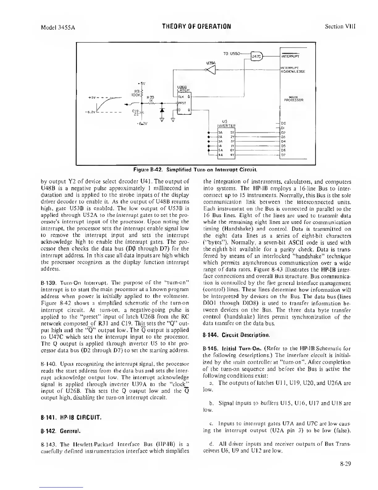
Figure
8-42.
Simplified Turn-on Interrupt Circuit.
by
output Y2 of device select decoder U41 . The output of
U48B is a negative pulse approximately 1 millisecond in
duration
and
is
applied to the strobe
inputs of
the display
driver decoder to enable it. As the output of U48B returns
high, gate US3B is
enabled.
The
low
output of US3B is
applied through US2A to the interrupt gates to set the pro-
cessor’s interrupt input of the processor. Upon noting the
interrupt, the processor sets the interrupt enable signal low
to remove the interrupt
input
and sets
the interrupt
acknowledge high to enable the interrupt gates. The
pro-
cessor then checks the data bus (D0 through D7) for the
interrupt address. In this case all data inputs are high which
the
processor recognizes as the display function interrupt
address.
8-139. Turn-On Interrupt. The
purpose
of
the “tum-on”
interrupt is to start the
main processor at
a
known program
address when
power
is initially
applied to the voltmeter.
Figure
8-42
shows a simplified
schematic of the turn-on
interrupt circuit. At
tum-on,
a
negative-going pulse is
applied to
the “preset” input of latch U26B from the RC
network composed_of R3
1
and
C19.
This sets the
“Q”
out-
put high and the
“Q”
output low.
The
Q
output is
applied
Co U47C
which
sets
the intermpt input to the processor.
The
Q
output is applied through
inverter
US to the pro-
cessor data bus (D2 through
07)
to set
the
starting address.
8-140.
Upon recognizing
the interrupt signal, the processor
reads the start address from
the data bus and sets the inter-
rupt
acknowledge output low. The interrupt acknowledge
signal is applied through inverter U39A Co
the
“dock^
input of U26B. This sets the
Q
output low and the
Q
output
high,
disabling
the turn-on interrupt circuit.
8-141.
HP-iB CIRCUIT.
8-142.
General.
the integration of instruments,
calculators, and computers
into systems. The HP-IB employs
a 16-line Bus to inter-
connect up to IS instruments.
Normally, this Bus is the sole
communication link between the
interconnected units.
Each instrument
on the Bus is connected
in
parallel
to the
16 Bus lines. Eight of the
lines are used to transmit data
while the remaining
eight lines are used for communication
timing (Handshake)
and control. Data is transmitted on
the
eight data lines as
a
series
of eight-bit characters
(“bytes"). Normally, a seven-bit
ASCII code is used with
the eiglith bit
available
for
a parity check. Data is trans-
ferred by means of an interlocked
“handshake” technique
which permits
asynchronous communication over
a wide
range of data rates. Figure 8-43
illustrates the HP-IB
inter-
face connections and overall Bus structure.
Bus communica-
tion is controlled
by the
five
general interface
management
(control) lines. These lines determine
how information will
be interpreted
by devices on the Bus. The
data bus (lines
DIOl through
D108) is used to transfer
information be-
tween devices on
the Bus. The three data
byte transfer
control
(handshake) lines permit
synchronization of
the
data transfer on the
data bus.
8-144.
Circuit
Description.
8-145.
Initial Turn-On.
(Refer
to
the HP-IB Schematic
for
the following
descriptions.) The interface
circuit is initial-
ized by the
main controller
at "turn-on”.
After completion
of the tum-on
sequence and before the Bus
is
active the
following conditions exist
:
a.
The
outputs of
latches
U1
1,
U19,
U20, and U26A are
low.
b.
Signal inputs to buffers
UlS, UI6, U17 and U18 are
low.
c. Inputs to interrupt gates U7A and
U7C
are low
caus-
ing the interrupt output
(U2A pin
3)
to be low
(false).
8-143. The
Hewlett-Packard Interface Bus (HP-IB) is a
d. All
driver
inputs and
receiver
outputs of Bus Trans-
carefully defined
instrumentation
interface which simplifies
ceivers U6, U9 and U12 arc low.
8-29
 Loading...


