Section VllI
THEORY OF OPERATION
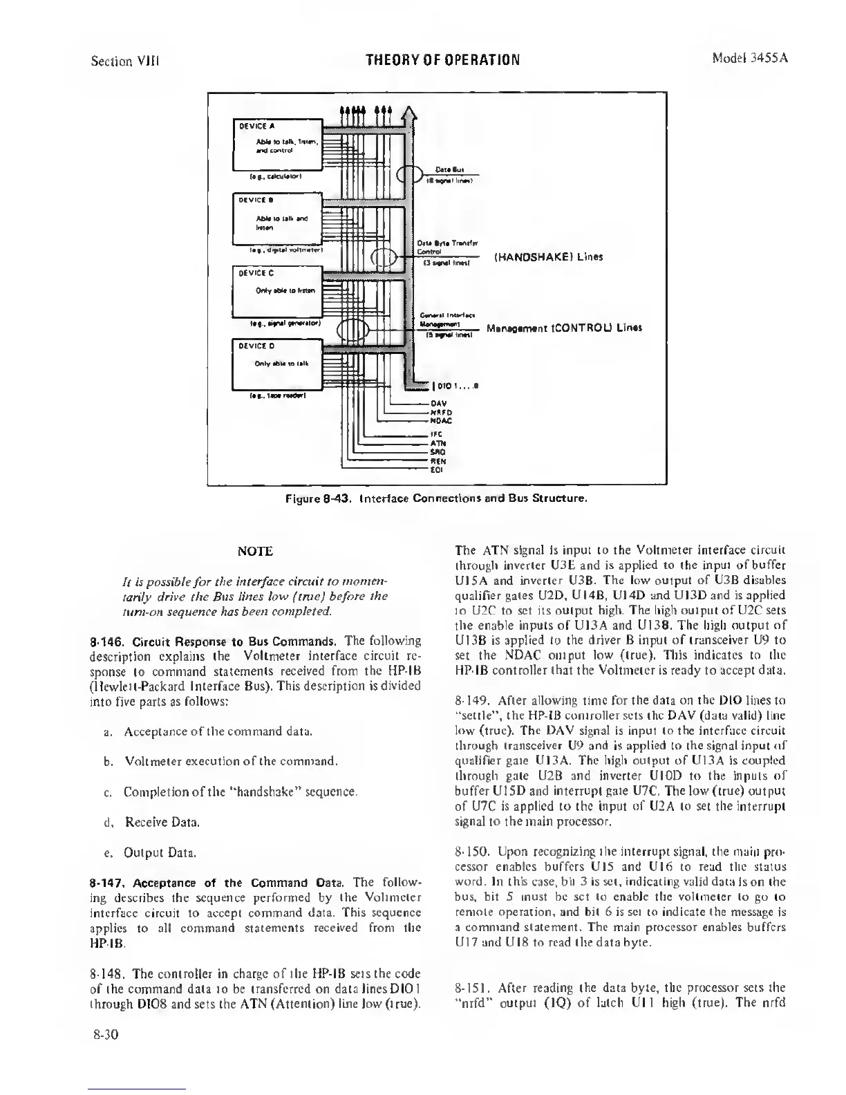
Model 3455A
NOTE
It
is possible
for
the interface
circuit to
momen-
tariiy
drive the Bus lines
low
(true) before
the
tum-on sequence has
been completed.
8-146.
Circuit
Response
to
Bus Commands.
The following
description explains the
Voltmeter interface circuit re-
sponse
to
command
statements received from the
HP-IB
(Hewlett-Packard Interface Bus). This description is
divided
into
five parts as follows:
a.
Acceptance of the command data.
b.
Voltmeter execution of the command.
c.
Completion of the ‘'handshake" sequence.
d.
Receive Data.
e.
Output Data.
8-147. Acceptance of the Command Data. The
follow-
ing describes the
sequence performed
by
the Voltmeter
interface circuit to accept command
data. This sequence
applies to all command
statements received from the
HP-IB.
8-148.
The
controller in charge of the HP-IB sets the code
of the command data to be transferred on data lines DIO I
through DIOS and sets the ATN
(Attention) line low (true).
The
ATN signal is input to the Voltmeter interface
circuit
through inverter U3E and is
applied to
the
input ofbuffer
UlSA and
inverter
U3B.
The low output of USB disables
qualifier gates U2D, UI4B, U14D and UI3D and is applied
to U2C to set its output high.
The high output of U2C sets
the
enable inputs of UlSA and U13B. The high output of
U13B is applied to the
driver B input
of
transceiver
U9
to
set
the NDAC output low (true). This indicates to the
HP-IB controller that the Voltmeter is ready to accept data.
8-
149. After
allowing
time for
the data
on
the DIO
lines to
“settle", the HP-IB controller sets the DAV (data valid) line
low
(true). The DAV signal is input to the interface circuit
through transceiver
U9
and
is applied
to the signal input of
qualifier gate UlSA. The high oulputofUlSA is coupled
through gate U2B and
inverter
UlOD to the inputs
of
buffer UlSD and
interrupt
gate U7C.
The low
(true) output
of U7C is applied to the input
of
U2A to set the interrupt
signal
to
the main
processor.
8-ISO.
Upon recognizing the interrupt signal, the
main pro-
cessor enables buffers UlS and UI6 to read the status
word. In this
case,
bit 3
is
set, indicating valid data
is on the
bus, bit 5 must be set to enable the voltmeter to
go
to
remote operation, and bit 6 is set to indicate the message
is
a command statement. The main processor enables buffers
U17 and UI8 to read the data byte.
8-151. After
reading
the data byte, the processor sets the
“nrfd"
output (IQ) of latch Ull high (true). The
nrfd
8-30
 Loading...


