NOTE 1
The
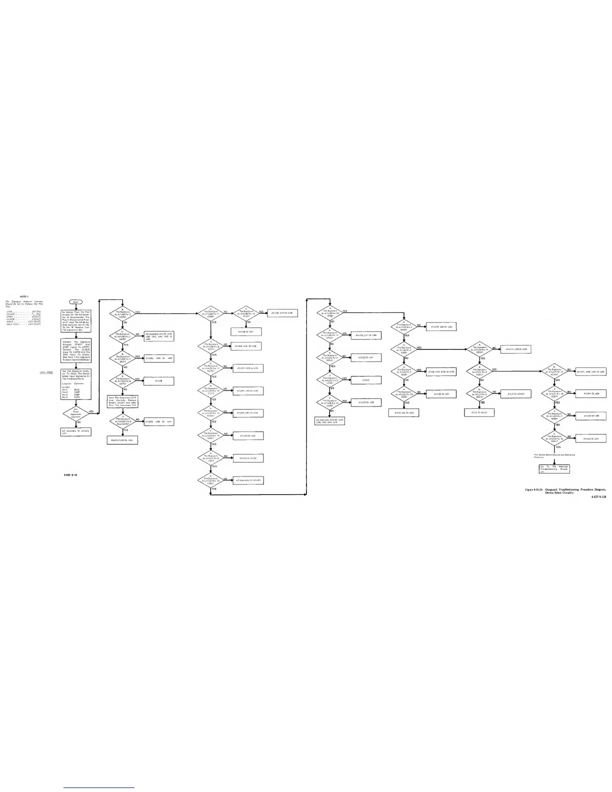
Signature Analyser Controls
Should Be Set As Follows For
This
Test:
LINE
ONflNJ
START
(IN)
STOP J'(OUT)
CLOCK
y(OUT)
HOLD
OFF (OUT)
SELF TEST OFF (OUT)
+5V; 02C2
Be Certain That; The Test
Jumper
On The A3 Assem-
bly
Is
Disconnected. The
Plug Is Disconnected Prom
A1J7 And
The HP-16
Ad-
dress Switches Are All Set
To The
"0"
Position. Tori*
The Instrument
ON.
Connect The
Signature
Analyzer START And
STOP Inputs To A3TP3.
Connect The CLOCK
Input To A3TP5 And The
GND Input To Chassis.
(See
Note 1 For Signature
Analyzer Control Settings.)
Use The Signature Analy-
zer To Check The Device
Select Input
Signatures At
The
Following Points:
Location
Signature
A1U33
Pin 1
6242
Pin 2
3A9F
Pin 3
2A6F
Pin
4 23F9
^
Are
These
Signatures
Correct?
The Signature
At A1U46
Pin
3
—.
5AP5?
/
The
Signature
At A1 U46
Pin
2
•\
U5P6?
/
The Signature
At A1U46
Pin
1
\
5857?
/
'
The Signature
^
At
A1U38 Pin II
\
CU60?
/
A3
Assembly A1U32. U34.
U39 U42. U44. U45
Or
U46.
The Signature^
At A1U38 Pin
8
•s. P737?
/
The Signature^N.
yes
At A1U38
Pin 12
\
P737?
A1U38
Or U41.
A1U36, U37.
Or U38.
A1 U36. U37
Or U38.
The Signature
^
At A1U39
Pin 10
\
2P58?
/
'’^The Signature^
At A1U32
Pin
3
\
02C2?
^
A1U19, U20 Or
U32.
The
Signature^
At
A1U39Pin11
•\
2FPA?
/
A1U18.U170r
U39
The Signature
At A1 U8
Pin
2
\
4C96?
/
The
Signature
At
A1U32 Pin
11
\
02C2?
A1U11.U26
Or
U32
A1U35, U43 Or U46.
''^The Signature^
At A1U32 Pm
4
\
2FPA?
^
A1U32
Or U41
The
Signature^
Ai A1U33
Pm 11
\
5UH2?
/
A1U21.U22or U33.
The
Signature
At
AlUSPin 1
\
4924?
^
A1U8.U16. U16,
Or U18.
The Signature
At AI U7 Pin 6
\
HC61?
/
The
Signature
^
At A1U41
Pm 13
\
AC4A? /
A1U41, U48,
U54
Or
U63
^
The
Signature^
At A1U39 Pin
9
V.
BAPS?
/
Turn The Instrument
OFF
And
Carefully Remove
RAM's A1U44
And
U45.
Turn The Instrument ON-
•"^The Signature^
AIA1U39 Pin
9
•s. Now 5AP5?^
The Signature
At
A1U32
Pin
5
•\
U754?
/
'
The Signature
^
At A1U33
Pm 12
\
7731?
A1U24. U25
0r
U33.
Tyes
/
'*
\
The Signature
YFS
A1U32
Or 039
1
At
A1U39 Pin
13
•
USP6?
The Signature
^
At A1U32
Pin 10
\
4924?
The
Signature
NO
^
The Signature
NO ».
1
AI 032 Or 041
AtA1U7
Pm
5
^
•
A1U7 Or A1U41 C AtA1U41
Pm
15
A1U41 Or
U64
H9H3?
0207?
The
Signature
^
At A1U33
Pin
13
\
H4CH?
J 1
>0
\
AI
029.
031 Or 033. 1 A104.
08.
Or U32.
A1U1 Or
A1U7
A1U38, U39
Or
U41.
A3
Assembly A1U32. U34.
U39.
U42. U44, U45
**^The Signature^
At A)U33
Pm
7
\
0066?
^
A1U33 Or U64
A3 Assembly
Or
A1U33,
U41.
RAM A1U44
Or 045.
The Signature
^
At
A1U33 Pm
14
\
5A8F?
/
A1U23
Of
U33
The
Signature
At A1U33
Pin
\
F541?
A1U33
0r 051
The
Signature
At
A1U33
Pin
9
\ 1764?
/
A1U33
Of A1Q7
The Device Select Circuits Are Operating
Correctly.
3455
-
0-19
Go To The Interrupt
Troubleshooting Proced-
ure.
The Signature
^
At A1U33 Pm 10
55PA?
/
A3
Assembly Or A1U33
Figure 8-H-24. Outguard
Troubleshooting Procedure Diagram.
Device
Select Circuitry.
8-J27/8-128
 Loading...


