280 Removal and replacement ENWW
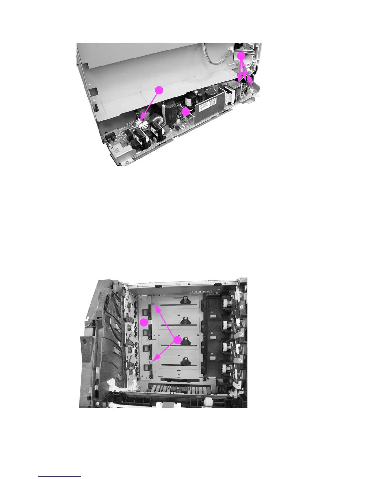
4 Disconnect four connectors (1) and remove the power supply (2).
Figure 6-128 Low voltage power supply PCB removal (2 of 2)
Memory controller PCB removal
1 Open the front door, remove the transfer unit, and the print cartridges. See Transfer unit
removal and Print cartridge removal.
2 Disconnect the left rod bracket from the front door by removing two screws from the bracket.
See Pick-up/feed assembly removal, step 4.
3 Remove two screws (1) and pull the shield plate (2) out. Adjust the position of the swing guide,
as required to access the screws. (The left swing guide has been removed for clarity in
illustrating this removal procedure. It is not necessary to remove the swing guide to remove
this PCB.)
Figure 6-129 Memory controller PCB removal (1 of 2)
2
1
1
1
2

 Loading...