I
,,,,
''
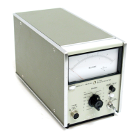
Model
4328A
Section
m
Paragraphs
3-1
to
3-19
I
"
,,
'I"
i
r"
!
SECTION
Ill
OPERATION
3-L
INTRODUCTION
3-2.
The
Model4328A
IS
effective
in
measuring
con-
tact
resistance
such
as
in
relays,
switches,
connec-
tors
and
incremental
resistance
of
diodes,
or
lead
resistance
of
integrated
circuits.
Measurement
is
made
by
the
4
terminal
method,
actually
utilizing
on
2
probes
One
current
lead
and
one
voltage
lead
are
incorporated
in
each
probe.
The
probes
are
branched
off
through
a
connector
in
the
probe
cord
that
leads
from
the
front
panel
and
the
user
can
rearrange
the
different
kinds
of
probes
OT
test
leads
at
will,
accord-
ing
to
the
form
of
the
sample.
This
section
includes
a
complete
de
scription
of
the
Mill
iohmmeter
operating
controls,
its
accessories,
characteristics
and
tech-
niques
of
uses
..
3-3.
The
range
of
4328A
extends
from
1
milliohm
to
100ohms
full
scale
in
a
1,
3,
10
sequence.
Maximum
sensitivity
IS
20p.
ohms.
3-4.
CONTROLS,
CONNECTORS
AND
INDICATIONS
3-5.
The
front
and
rear
panel
controls,
conneetors
and
mdicators
are
explained
in
Figure
3-1
and
3-2,
The
descriptions
are
keyed
to
the
corresponding
items
which
are
i.nd'lcated
on
the
fi.gure
3-6.
BATTERY
OPERATION
3-7.
The
HP
4328A Option
001
can
operate from a rechargea-
ble
Nickel-Cadmium battery
or
ac hne power. Continuous bat-
tery operation is poss1ble for approximately
15
hours after a
full charge
..
The
4328A automatically operates on
1ts
mternal
batteries whenever the ac
lme power IS disconnected,
and
the
batteries are
continually charging when the power cable
is
con-
nected
to
the power lme, when
the
LINE lamp
is
lit
3-8,
Before operatmg the 4328A
on
battenes, check the bat-
tery voltage with the BATT.
TEST
button
..
When the BATT
TEST button
is
pressed, the
pointer
of
mater indicates the in-
ternal battery voltage
..
If
the
pointer
is
in the range
of
BAT.
CHARGED
of
the meter, the
battery
voltage
is
h1gh
enough
to use
..
If the pointer IS out
ot
the
range
of
BAT
CHARGED,
the battery must be recharged first..
3-9,
The battery can be charged using the following proce-
dure (when in the
BAT..
CHARGED
range
or
out
of
the BAT
CHARGED
range)
I)
Connect the power plug
to
the
ac hne,
and
set the LINE
sw1tch
to FAST CHARGE..
The
LINE lamp
is
lit
and
mdicates
the
battery
1s
charging
..
2)
Charge
the
battery unul
the
pointer
is
in the range
of
BAT.
CHARGED
by
pressmg
the
BATT.
TESL
It
takes
apprmumately 4 hours
to
charge up a full discharged bat-
tery mto the BAT
CHARGED
range, and takes approx-
Imately
48 hours to fully charge
..
CAUTION
The
four
Nickel-Cadmium
batteries
in
the
Option
001
are
m
hermetically-sealed
con-
tainers
Under
high
temperatures
(above
50°
C),
hydrogen
m
the
hermetically-
sealed
battery
container
can
build
up
to
high
pressure
causing
damage
to
the
bat-
teries
and
or
the
mstrument
The
user
must
be
cognizant
of
temperature
ex:-
tremes
while
charging
the
batteries.
Do
not
charge
batteries
when
temperature
is
above
40°C
..
3-10
Instrument
Temperature
Range
3-11,
Model4328AOption001
has
certain
temperature
limitations_
Operatmg
temperature
upper
limits
for
battery
operation
are
lower
compared
with
convention-
al
ac
operatwn
(Oo
C
to
50°
C).
Internal
temperatures
in
ex:cess
of
50°
Care
quite
easy
to
obtain
tf
the
instru-
ment
is
left
m
the
sun,
even
if
the
air
temperature
is
quite
moderate
A
good
practice
is
to
be
certain
that
the
instrument
IS
not
stored
or
operated
in
direct
sun-
light
to
avoid
the
possibility
of
reduced
performance.
Keep
this
limitatwn
in
mind
when
operating
in
field
conditions
to
obtam
safe
and
stable
operation.
CAUTION
Nickel-Cadmium
cells
in
this
instrument
are
hermetically-sealed
Damage
to
cells
may
occur
if
exposed
to
extremely
high
temperatures
(above
50° C)
3-12.
MEASUREMENT
3-13.
Measurement
is
made
by
the
4
terminal
method
to
obtam
accurate
measurement
of
Low
resistance,
actually
two
2-termmal
probes
are
used
so
that
opera-
tton
of
the
instrument
is
quite
easy
The
probes
fur-
nished
in
Model4328A
are
16005A
probe,
16006A
probe
and
16007
A/B
conventional
4
termmal
test
leads.
3-14.
Under
no
conditions
will
voltage
across
the
sample
exceed
20mV
peak,
even
in
the
case
of
incor-
rect
range
settings.
When
the
correct
range
setting
is
used,
voltage
across
the
sample
is
less
than
200f.1V
peak.
For
optimum
use
of
the
instrument,
range
should
be
set
on
a
higher
range
when
making
the
mi-
tial
connection
followed
by
swttching
the
selector
to
the
appropriate
lower
range.
3-15.
OPERATING
PROCEDURE
3-16.
Figure
3-3
illustrates
operating
procedure.
3-17.
MEASURING
VOLTAGE
ON
SAMPLES
3-18.
When
the
voltage
applied
between
the
contact
is
high,
the
oxidized
film
formed
between
the
contact
is
destroyed
thereby,
and
the
resistance
value
me
as-
ured
may
be
smaller
than
under
actual
use.
More-
over,
once
this
happens,
it
wi.ll
never
recover
the
former
conditwn
even
if
the
voltage
or
the
current
is
cut
off
3-19.
According
to
the
recommended
standard
of
IEC
(lnternahona
Electrotechnical
CommissLOn),
meas-
urement
of
contact
rest
stance
by
ac
should
be
conducted
3-1

 Loading...