EasyManuals Logo
Home>HP>Measuring Instruments>4328A

HP 4328A Service Manual

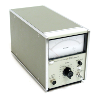
HP 4328A
125 pages
To Next Page IconTo Next Page
To Previous Page IconTo Previous Page
Page #20 background imageLoading...
Page #20 background image
Section
III
Paragraphs
3-35
to
3-46
3-35.
Probe
Installati.on
3-36..
Plug
in
the
probes
to
the
connector
at
the
end
of
16l43A
Probe
Cable.
Note
that
the
probe
plugs
must
be
oriented
correctly
before
plugging
m.
1)
Connector
at
the
end
of
probe
cable
has
4-
contacts
Each
pairof
closely--spaced
contacts
comprise
one
set
of
probe
contacts.
2)
Plug
the
probe
pms
in
to
the
connector
such
that
the
off
set
Side
faces
outwards..
Refer
to
Figure
3-5.
t
16143A
Figure
3-5.
Probe
Installation
3-37.
16005A
CLip-type
Probe
3-38.
General
purpose,
alligator-jaw
contacts
pro-
vide
positive
gripping
of
samples.
Upper
contact
(marked
"V"l
is
voltage
termmal
and
lower
contact
is
current
terminal.
When
using
this
probe
in
1
mn
range,
It
is
not
alway-s
possible
to
measure
the
sample
because
of
extreme
deflectwn
of
the
meter.
Figure
3-6
shows
16005A
Clip-type
Probes.
Figure
3-6.
16005A
Clip-type
Probes
3-39.
16006A
Pin-type
Probe
j
/
3-40.
Probe
tip
is
a
voltage
terminal
and
outer
con-
ductor
ts
a
current
terminal.
Probe
tip
is
spring-
loaded,
so
that
both
terminals
firmly
contact
the
sample
under
test.
This
probe
LS
usefulfor
press-an
contact
measurement
such
as
printed
board
conduc-
tivity
measurements.
When
using
this
probe
m
lmn
range,
itis
notalways
possibleto
measure
the
sample
because
of
extreme
deflection
of
the
meter.
(See
Figure
3-7).
3-6
---.jo._--~-
.~-
__
L+_,._-.._._,j...
Model
4328A
Figure
3-7.. 16006A
Pin-type
Probes
3-41.
16007A!B
Test
Leads
3-42..
These
are
provided
for
standard
4
-terminal
measurements..
Each
pair
of
testlead
has
a
separate
alligator
clip
voltage
and
current
terminaL
16007A
is
furnished
with
a
red
cover
the
16007B
with
a
black
cover..
The
black
test
lead
is
the
voltage
terminal
and
the
grey
test
lead
IS
the
current
terminaL
(See
Figure
3-8)
Figure
3-8..
16007A/B
Test
Leads
3-43.
NOTES
ON
OPERATION
3-44..
IN
USING
THE
1 AND
3m
OHM
RANGES,
CONNECTION
OF
CURRENT
TERMINALS
TO
THE
SAMPLE
MUST
BE
A
FIRM,
POSITIVE
CONTACT.
3-45..
With
Model
4328A,
the
internal
resistance
of
the
constant
current
generator
is
approximately-equal
to
the
set
range
x500
Therefore,
at
1m
ohm
and
3m
ohms
ranges,
the
internal
resistances
are
500m
ohms
and
1.
5
ohms
respectively..
Excessive
resist-
ance
at
the
probe
contact
can
therefore
relatively
larger
error
than
on
other
ranges,
The
quahty
of
the
connection
of
the
probes
to
the
sample
may
be
deter-
rowed
by
applying
pressure
on
the
connection
point
and
noting
if
the
meter
needle
deflects..
Very
poor
contact
or
no
contact
whatsoever
1s
mdicated
by-
a
deflection
off-scale
3-46..
IN
USING
THE
1 AND
3m
OHM
RANGE
LARGE
ELECTRICALLY
CONDUCTIVE
MATERIALS
SHOULD
NOT
BE
PLACED
CLOSE
TO
THE
PROBES
OR
THEIR
CABLES,

Table of Contents

Questions and Answers:

Question and Answer IconNeed help?

Do you have a question about the HP 4328A and is the answer not in the manual?

HP 4328A Specifications

General IconGeneral
BrandHP
Model4328A
CategoryMeasuring Instruments
LanguageEnglish

Related product manuals