Section
Ill
Figure
3-3
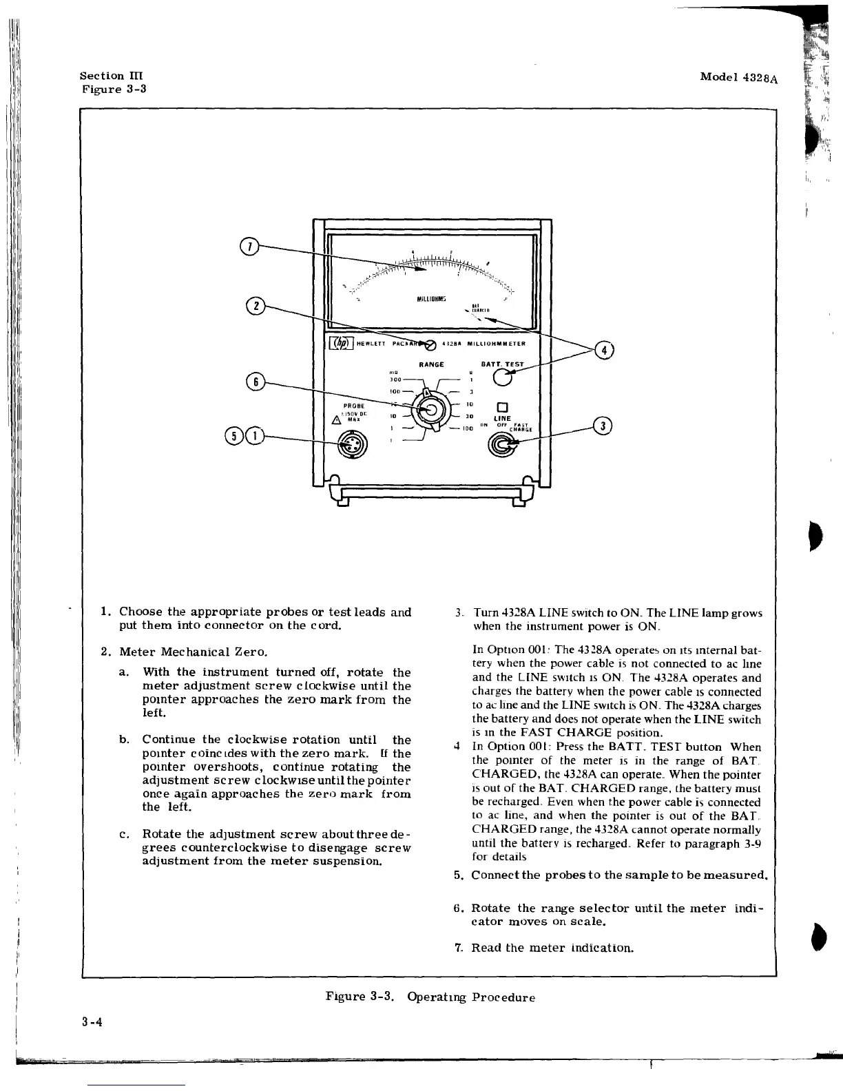
1.
Choose
the
appropriate
probes
or
test
leads
and
put
them
into
connector
on
the
cord.
2.
Meter
Mechanical
Zero.
a.
With
the
instrument
turned
off,
rotate
the
meter
adjustment
screw
cLockwise
until
the
pomter
approaches
the
zero
mark
from
the
left.
b.
Continue
the
clockwise
rotation
until
the
pomter
coinctdes
with
the
zero
mark.
[f
the
pointer
overshoots,
continue
rotating
the
adjustment
screw
c
lockw1se
until
the
pointer
once
again
approaches
the
zero
mark
from
the
left.
c.
Rotate
the
adJustment
screw
aboutthree
de-
grees
counterclockwise
to
disengage
screw
adjustment
from
the
meter
suspension.
Model
4328A
3..
Turn
4328A LINE switch to
ON
..
The LINE
lamp
grows
when the instrument power is
ON
..
In
Option
001: The
43~8A
operate'>
on
Its
mternal
bat-
tery when the power cable
is
not
connected
to
ac Ime
and
the LINE switch
IS
ON. The 4328A operates
and
charges the battery when the power cable
IS
connected
to
ac !me
and
the LINE switch is ON. The 4328A charges
the battery
and
does not operate when the
LINE
switch
ism
the
FAST
CHARGE
position.
4 In
Option
001::
Press the BATT.
TEST
button
When
the
pomter
of
the meter is in the range
of
BAT..
CHARGED,
the 4328A can operate
..
When
the
pointer
is
out
of
the
BAT..
CHARGED
range, the
battery
must
be recharged
..
Even when the power cable
i'>
connected
to ac line,
and
when the
pomter
is
out
of
the
BAL
CHARGED
range, the
4328A
cannot
operate
normally
until
the
battery
Is
recharged
..
Refer to
paragraph
3-9
for details
5.
Connect
the
probes
to
the
sample
to
be
measured.
6.
Rotate
the
range
selector
until
the
meter
indi-
cator
moves
on
scale.
7.
Read
the
meter
indication.
Figure
3-3.
Operatmg
Procedure
3-4