EL-MF877-00 Page 2
Template Revision C
Last revalidation date 09-May-2018
HPI instructions for this template are available at EL-MF877-01
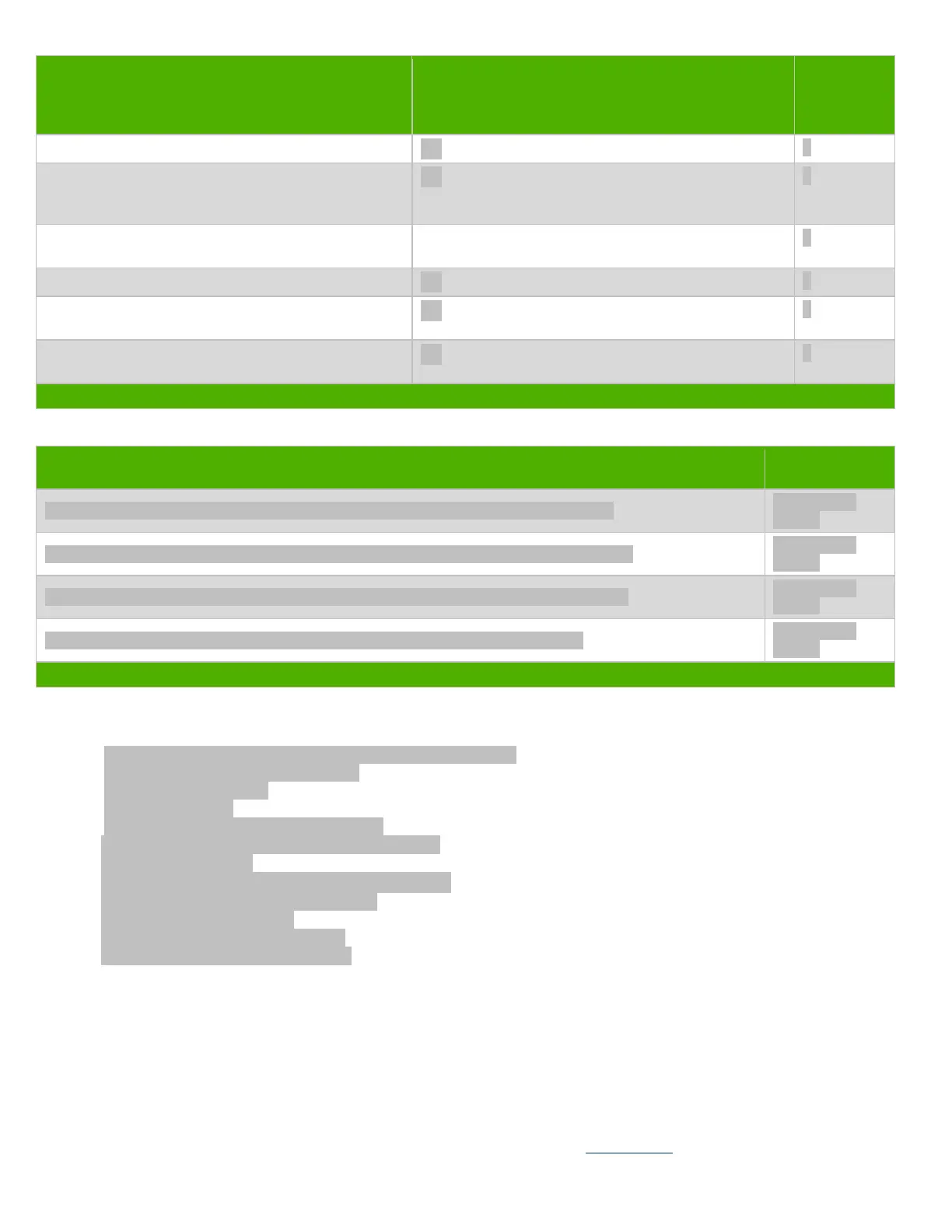
Quantity of
items
included in
product
Plastics containing Brominated Flame Retardants
weighing > 25 grams (not including PCBs or PCAs
already listed as a separate item above)
Components and parts containing toner and ink,
including liquids, semi-liquids (gel/paste) and toner
Include the cartridges, print heads, tubes, vent
chambers, and service stations.
Components and waste containing asbestos
Components, parts and materials containing refractory
ceramic fibers
Components, parts and materials containing
radioactive substances
List the type and size of the tools that would typically be used to disassemble the product to a point where components and
materials requiring selective treatment can be removed.
Tool Size (if
applicable)
Description T15 screw driver (Disassemble 3 pcs screws for side bkt and main bkt)
Description T15 screw driver (Disassemble 3 pcs screws for ODD cage and main bkt)
Description T15 screw driver (Disassemble 2 pcs screws for PCI cover and main bkt)
Description T15 screw driver (Disassemble 4 pcs screws for MB and main bkt)
3.0 Product Disassembly Process
3.1 List the basic steps that should typically be followed to remove components and materials requiring selective treatment
including the required steps to remove the external enclosure:
1. Loosen thumb screw and remove Access panel from hosing
2. Pull off ODD SATA con &ODD power con.
3. Remove ODD from hosing
4. Remove front bezel.
5. Loosen 3 screws on side bkt then remove it.
6. Loosen 3 screws on front brkt then remove ODD cage.
7. Pull off all cables on MB.
8. Loosen 2 screws on Rear brkt then remove System Fan.
9. Loosen 2 screw on PCI cover then remove it.
10. Remove VGA card from hosing.
11. Loosen 4 screws on MB then remove it.
12. Loosen 4 screws on PSU then remove it.
3.2 Optional Graphic. If the disassembly process is complex, insert a graphic illustration below to identify the items contained in the
product that require selective treatment (with descriptions and arrows identifying locations).
 Loading...